Ultraviolet air purification systems

a technology of ultraviolet radiation and purification system, which is applied in the direction of air quality improvement, combination devices, and dispersed particle filtration, etc., can solve the problems of increasing costs, cooling coils often reaching the point where they cannot be effectively cleaned, and contaminants can pose health hazards in buildings and other enclosed environments

Inactive Publication Date: 2004-11-16
TURCOTTE MARK
View PDF29 Cites 58 Cited by
  • Summary
  • Abstract
  • Description
  • Claims
  • Application Information

AI Technical Summary

Problems solved by technology

These contaminants can pose a health hazard in buildings and other enclosed environments, and have been linked to Sick Building Syndrome and Building Related Illness, among other conditions.
Efforts to eliminate these hazards has led to increased costs, particularly in commercial settings, for air handler coil cleaning.
Because of the huge size and particularly the depth of cooling coils in commercial and similar settings, the cooling coil often reaches a point where it can no longer be effectively cleaned.
Many coils are 12" thick or more; after a period of years the center of those coils cannot be easily reached for cleaning.
Such procedures are time consuming and costly.
Ultraviolet devices currently used in connection with large air handling systems to eliminate contaminants are limited in their ability to efficiently and completely clean the entire coil.
These devices are costly to design and maintain.
In addition, devices that are disposed inside the duct of an air conditioning system are prone to increased wear and deterioration due to vibration and conditions inside the system.

Method used


Image

  • Ultraviolet air purification systems
  • Ultraviolet air purification systems
  • Ultraviolet air purification systems

Examples


Embodiment Construction

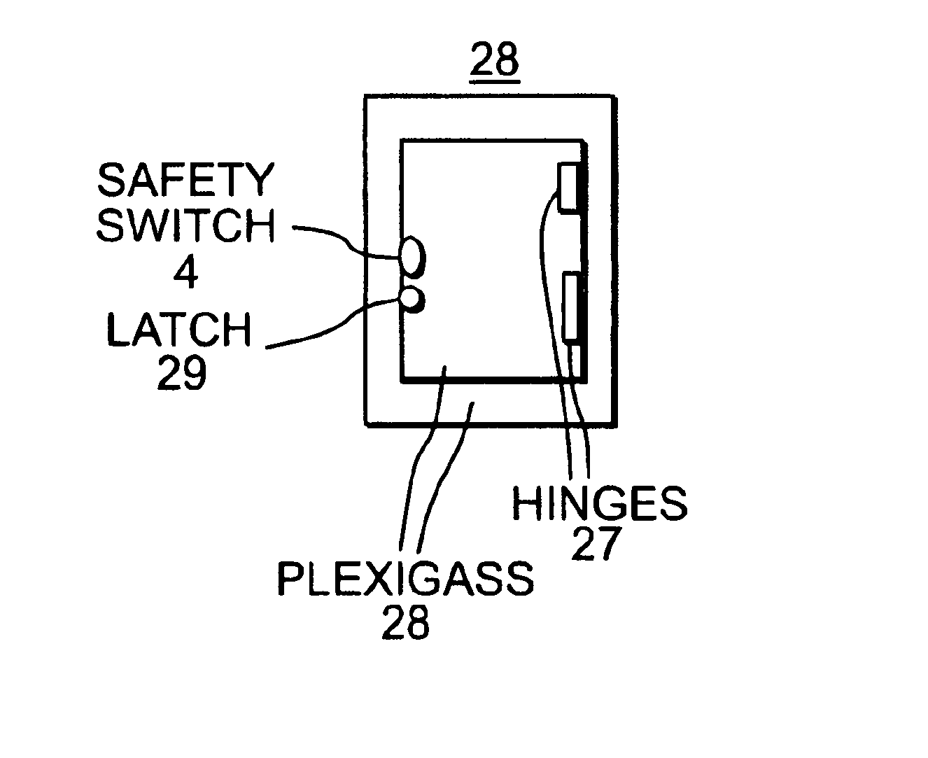
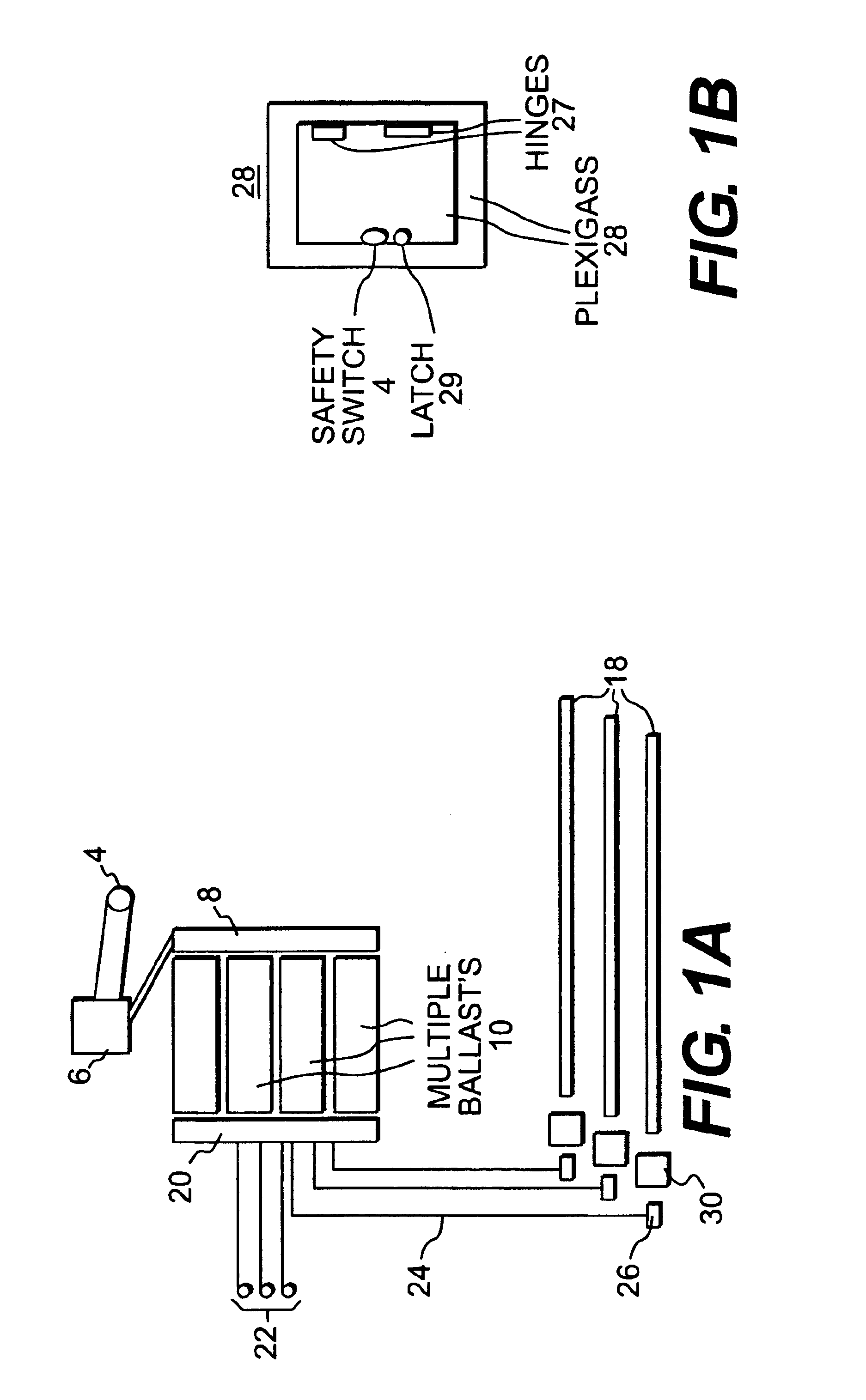
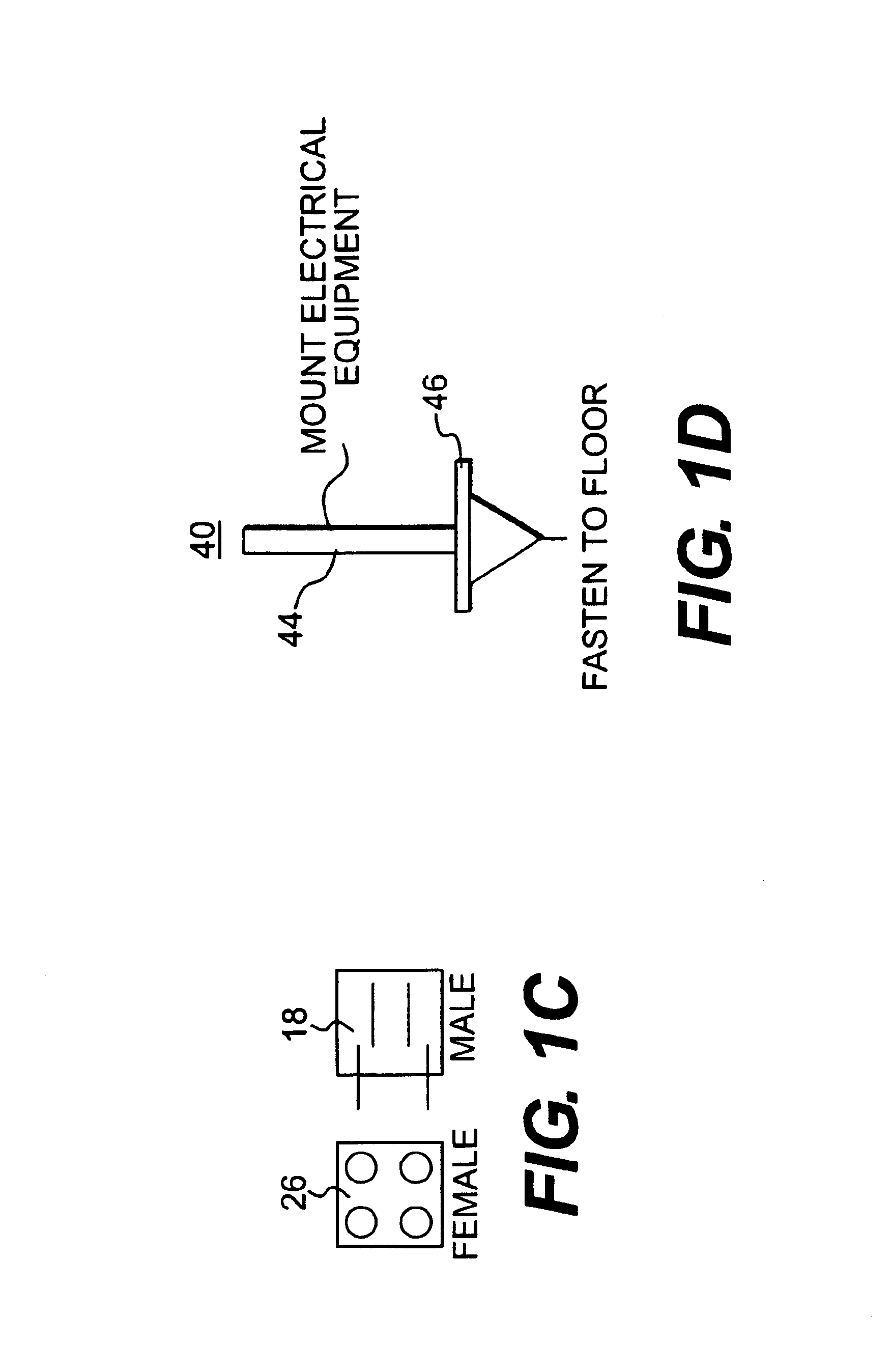
As embodied and broadly described herein, the present invention is directed to air purification devices and kits for installing a customized ultraviolet air purification device. Devices according to the invention can be used in all settings including both commercial and residential. The present invention is a substantial improvement over existing devices that are currently available for use in either commercial or residential settings. The existing devices are expensive due to custom manufacturing requirements and, consequently, can also be difficult to customize. The invention is designed to eliminate mold, mildew, bacteria and viruses, or otherwise render these contaminants ineffective to cause disease. The invention purifies air passing by the lamps and also neutralizes stationary contaminants within the effective radius of the lamp and further allows for the disinfection and purification of air as that air travels past the UV lamps.

Ultraviolet devices of the invention have the p...


PUM

PropertyMeasurementUnit
thicknessaaaaaaaaaa
voltageaaaaaaaaaa
voltageaaaaaaaaaa

Abstract

The present invention relates to ultraviolet air purification devices and custom component kits useful residential and commercial settings. Apparatus and kits according to the invention include an electrical control relay, a safety switch, and a separate ballast for each lamp. When multiple lamps are used, a suppressor ballast is used to protect the lamps from electrical surges. Terminal strips are included so multiple ballasts and lamps can be used as part of the electrical configuration. The invention allows for UV-C bulbs and is designed so that only the lamps and their connectors must be disposed in the path of the air flow. The lamps are easily installed by pushing into a connector on one end. Supports for the end and the middle of the bulbs may be used in installation. LED indicator lights show if each lamp is receiving the electrical charge. Multi-faceted tin reflectors may be installed on each end.

Description

1. Field of the InventionThis invention relates to methods for purifying the air, and more specifically, to systems and methods for purifying air using ultraviolet radiation that are easily customized to accommodate different air handling systems, allow for remote location of certain components and provide superior purification levels.2. Description of the BackgroundUltraviolet (UV) germicidal irradiation has been known by scientist for over 80 years to kill fungi, bacteria, virus and other contaminants. These contaminants can pose a health hazard in buildings and other enclosed environments, and have been linked to Sick Building Syndrome and Building Related Illness, among other conditions.A number of different systems have utilized ultraviolet radiation in order to improve air quality. Some devices are designed for use in large air handling systems while others are used to purify air on a smaller scale, such as in a single room. For example, with respect to purifying airflow in an...

Claims


Application Information

Patent Timeline
Patent Type & Authority Patents(United States)
IPC IPC(8): A61L9/18A61L9/20F24F3/16
CPCA61L9/20F24F3/166F24F2003/1667F24F8/192F24F8/22Y02A50/20
Inventor TURCOTTE, MARK
Owner TURCOTTE MARK
Why Eureka
Try Eureka