Centrifugal blower having noise-reduction structure

a centrifugal blower and noise reduction technology, applied in the direction of machines/engines, stators, liquid fuel engines, etc., can solve the problem of low-frequency noise and other problems

Inactive Publication Date: 2004-11-23
DENSO CORP
View PDF13 Cites 47 Cited by
  • Summary
  • Abstract
  • Description
  • Claims
  • Application Information

AI Technical Summary

Benefits of technology

According to the present invention, in a centrifugal blower, a centrifugal fan is disposed in a scroll casing to have a space between the centrifugal fan and the scroll casing at a nose portion, through which a scroll start side and a scroll finish side communicate with each other in the scroll case. The scroll case has an end in the vicinity of the nose portion, at a reverse side with a rotation direction of the centrifugal fan. In addition, the end is tilted relative to a direction parallel to the rotation axis, toward the rotation direction, from a side of the suction port to a side opposite to the suction port. Accordingly, a re-circulation air flow from an air outlet side (scroll finish side) into the space between the outer periphery of the centrifugal fan and the inner wall of the scroll case in the nose portion, can be introduced toward a downstream air-blowing side of the centrifugal fan with the air blown by the centrifugal fan, without being reversely introduced between blades of the centrifugal fan. Thus, it can restrict an interference between the re-circulation flowing air and the sucked air, and thereby reducing the low-frequency noise.
Alternatively, in the present invention, the scroll case has a first wall part on the side of the suction port, and a second wall part on the side opposite to the suction port, in the vicinity of the nose portion. In addition, the first wall part is disposed to protrude from the second wall part toward a reverse side with the rotation direction. Even in this case, the same advantage described above can be obtained.
Preferably, in a predetermined range from the nose portion in the rotation direction, a first clearance dimension between an outer periphery of the centrifugal fan and an inner wall of the scroll casing on the side of the suction port, is smaller than a second clearance dimension between the outer periphery of the centrifugal fan and the inner wall of the scroll casing on the side opposite to the suction port. In this case, the NZ noise and the specific noise can be further reduced while the low-frequency noise can be reduced.
Preferably, a scroll angle of the scroll casing is continuously changed in such a manner that the first clearance dimension is equal to the second clearance dimension in a range of the scroll angle between 20 degrees and 135 degrees. Therefore, noise generated in the blower can be effectively reduced. Further, in the nose portion, a ratio of the second clearance dimension to an outer diameter of the centrifugal fan is in a range of 0.1-0.16. In this case, the low-frequency noise, the NZ noise and the specific noise can be readily reduced.

Problems solved by technology

In addition, when a dimension (i.e., scroll radius) between a rotation axis of the centrifugal multi-blade fan and the scroll casing is simply set to become larger from a scroll start portion toward a scroll finish portion of the scroll casing, a low-frequency noise may be caused.

Method used


Image

  • Centrifugal blower having noise-reduction structure
  • Centrifugal blower having noise-reduction structure
  • Centrifugal blower having noise-reduction structure

Examples


Embodiment Construction

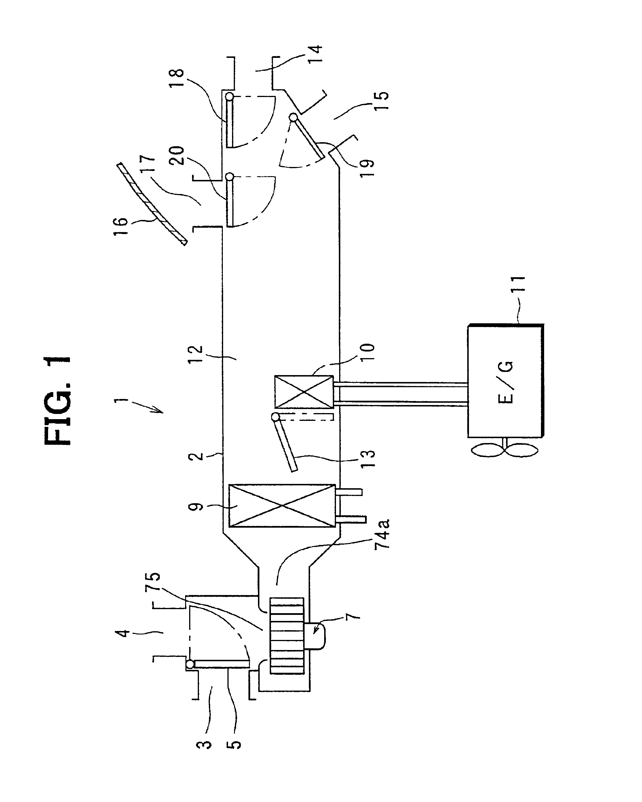
A preferred embodiment of the present invention will be described hereinafter with reference to the accompanying drawings. In this embodiment, a centrifugal blower 7 according to the present invention is typically used for an air conditioner 1 for a vehicle having a water-cooled engine.

The air conditioner 1 shown in FIG. 1 includes an air-conditioning case 2 defining an air passage through which air flows into a passenger compartment. At an upstream air side of the air-conditioning case 2, an inside air introduction port 3, through which inside air inside the passenger compartment is introduced, and an outside air introduction port 4, through which outside air outside the passenger compartment is introduced, are provided. An inside / outside air switching door 5 is disposed for selectively opening and closing the inside air introduction port 3 and the outside air introduction port 4. The inside / outside air switching door 5 can be opened and closed by using a driving unit such as a ser...


PUM


Abstract

In a predetermined range from a nose portion toward a scroll finish side in a scroll casing of a centrifugal blower, a first clearance dimension on a side of a suction port between an outer periphery of a centrifugal fan and a side plate of the scroll casing is set smaller than a second clearance dimension on a side opposite to the suction port between the outer periphery of the centrifugal fan and the side plate of the scroll casing. In addition, in the vicinity of the nose portion, a first wall part of the scroll casing on the side of the suction port protrudes toward a scroll finish side, from a second wall part of the scroll casing on the side opposite to the suction port.

Description

This application is claims foreign priority based upon Japanese Patent Applications No. 2001-76959 filed on Mar. 16, 2001, and No. 2002-10324 filed on Jan. 18, 2002, the contents of which are hereby incorporated by reference.1. Field of the InventionThe present invention relates to a centrifugal blower including a centrifugal multi-blade fan having plural blades arranged around a rotation axis. More particularly, the present invention relates to a noise-reduction structure for reducing noise caused in the centrifugal blower. The present invention is suitably used for a blower of a vehicle air conditioner.2. Description of Related ArtIn a conventional centrifugal blower described in JP-U-50-82706 or in JP-U-54-97805, a nose cap at a side of a suction port is made smaller than a nose cap at a side opposite to the suction port, so that a NZ noise is reduced while it can prevent an air-blowing amount from being reduced and a specific noise from being increased. Here, the NZ noise is a n...

Claims


Application Information

Patent Timeline
Patent Type & Authority Patents(United States)
IPC IPC(8): F04D29/42B60H1/00F04D29/44F04D29/66
CPCF04D29/422
Inventor SAKAI, MASAHARUMATSUNAGA, KOUJI
Owner DENSO CORP
Why Eureka
Try Eureka