Fuel injection valve

a fuel injection valve and valve body technology, applied in the direction of fuel injection apparatus, fuel feed system, spraying apparatus, etc., can solve the problems of valve needle tilting danger, restricted degree, and malfunction of injector

Inactive Publication Date: 2004-11-30
ROBERT BOSCH GMBH
View PDF9 Cites 16 Cited by
  • Summary
  • Abstract
  • Description
  • Claims
  • Application Information

AI Technical Summary

Benefits of technology

The fuel injector according to the present invention with the distinguishing characteristics of claim 1 has the advantage relative to the related art on the one hand that the radial and axial play of the valve needle brought about by the two guide sleeves and by the central opening in the armature provide so much freedom of movement that tilting is impossible, and on the other that the individual components of the fuel injector can be manufactured with a low degree of complexity, and low production costs, for example by deep drawing, since the design according to the present invention presents a very high tolerance for manufacturing errors in the components.By the further measures listed in the dependent claims, advantageous further developments of the fuel injector described in the main claim are possible.Also advantageous is the wedge-shaped or spherical design of the guide sleeves, and the corresponding elevations in the faces of the armature, which compensate for angular misplacements of the valve needle relative to the longitudinal axis of the fuel injector.In addition, the symmetrical design, i.e. the rotatable mounting of the valve needle in the sealing seat, is advantageous, since this means that even in the event of major center offsets the valve needle can always align itself optimally.Through the gaps between the guide sleeves and the armature, in addition, a slight pre-acceleration of the valve needle can be achieved, before the armature lifts the valve needle off the sealing seat. By this means the opening times or the amounts of fuel metered can be improved.

Problems solved by technology

One disadvantage with the fuel injector known from German Laid-Open Patent DE-OS 33 14 899 is the incomplete elimination of bounce, and on the other hand the arrangement of the armature and valve needle also makes it possible for the latter to tilt or stick as a result of center offset between the valve needle and the armature.
This defect is intensified by manufacturing errors in the individual components of the fuel injector, leading to malfunctions of the injector.
The particular disadvantage of this arrangement lies in the restriction of the degree of freedom in the movement of the valve needle through the guide sleeve joined with the injector housing and thus in the danger of the valve needle tilting.
Countering this disadvantage requires components that are manufactured extremely accurately, and these are characterized by high cost and very complex manufacture.

Method used


Image

  • Fuel injection valve
  • Fuel injection valve
  • Fuel injection valve

Examples


Embodiment Construction

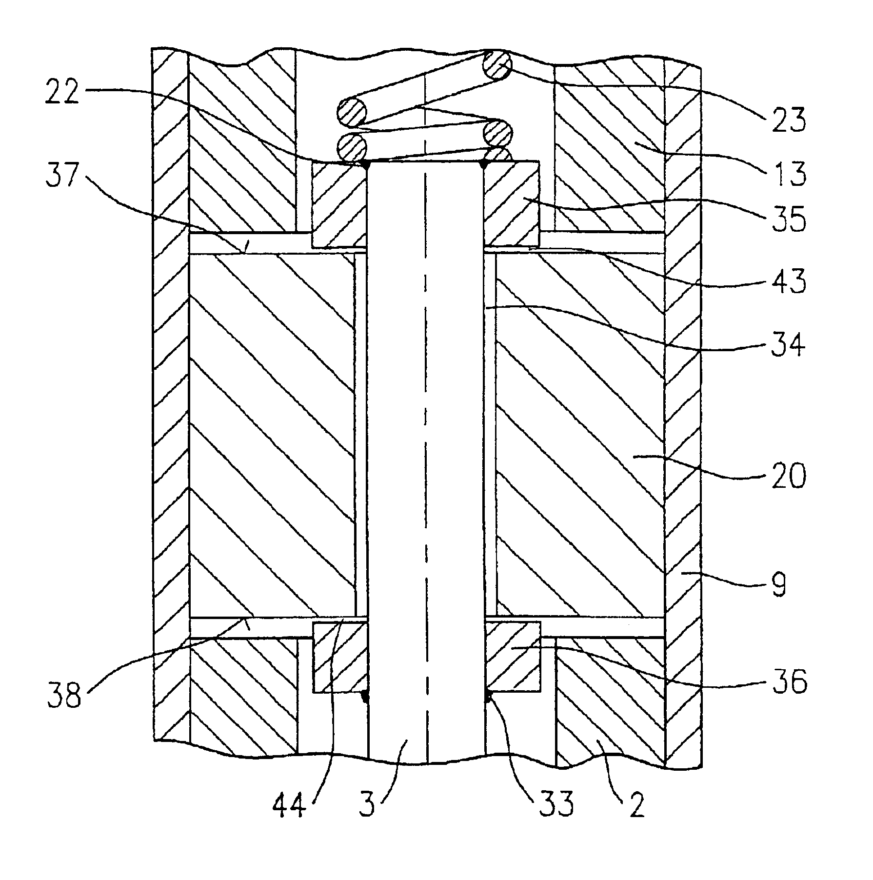
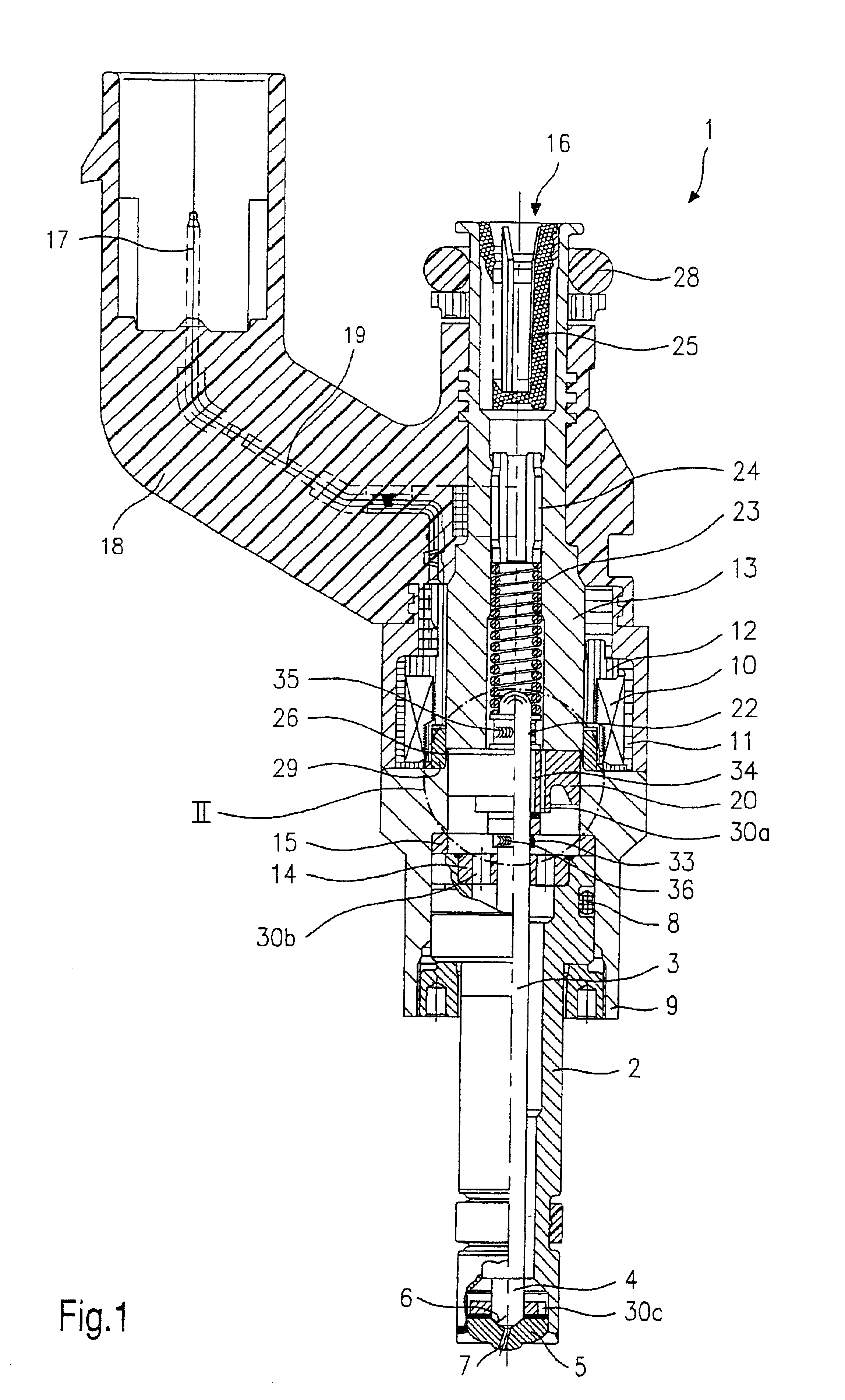
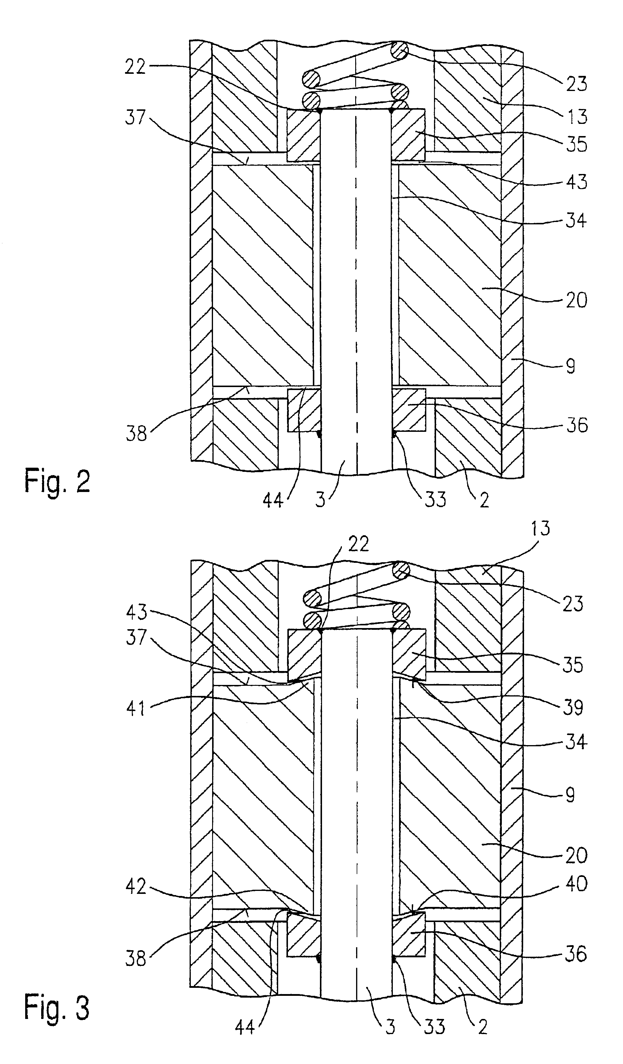
A fuel injector 1 is constructed in the form of a fuel injector for fuel injection systems on spark-ignition internal combustion engines, in which the fuel-air mixture is compressed. Fuel injector 1 is particularly suitable for direct injection of fuel into a combustion chamber, not shown, of an internal combustion engine.

Fuel injector 1 is composed of a nozzle body 2 into which a valve needle 3 is guided. Valve needle 3 acts upon a valve closing member 4, which acts together with a valve seat surface 6 situated on a valve seat body 5 to compose a sealing seat. In fuel injector 1 in the exemplary embodiment the opening action is inwards, and fuel injector 1 has a spray orifice 7.

Valve needle 3 is rotatably mounted in the sealing seat in order to permit simple guidance of the needle. This has no impact on the imparting of swirl by fuel injector 1, since valve needle 3 is symmetrical around its axis of rotation.

Nozzle body 2 is sealed against external pole 9 of a solenoid 10 by a seal...


PUM


Abstract

A fuel injector for fuel injection systems of internal combustion engines has a solenoid, with a valve needle pressed in the closing direction by a return spring to activate a valve closing member, which together with a valve seat surface forms a sealing seat, and an armature in friction-locking connection with a valve needle. A first guide sleeve and a second guide sleeve are connected to the valve needle. The armature has radial play with respect to the valve needle as a result of the central opening, the diameter of which is greater than the diameter of the valve needle.

Description

BACKGROUND INFORMATIONThe invention is based on a fuel injector according to the definition of the species of the main claim.An electromagnetically operable fuel injector is already known from German Laid-Open Patent DE-OS 33 14 899 in which for the purposes of electromagnetic activation an armature acts together with an electrically excitable solenoid and the stroke of the armature is transmitted by way of a valve needle to a valve closing member. The valve closing member works together with a valve seat. The armature is not rigidly attached to the valve needle, but is arranged with axial movement relative to the valve needle. A first return spring exerts pressure on the valve needle in the closing direction and thus holds the fuel injector closed when the solenoid is non-current-bearing and thus not excited. The armature is pressed by a second return spring in the stroke direction such that in its idle position the armature is touching a first stop provided on the valve needle. Wh...

Claims


Application Information

Patent Timeline
Patent Type & Authority Patents(United States)
IPC IPC(8): F02M61/20F02M61/00F02M61/16F02M51/06
CPCF02M51/0671F02M51/0685F02M61/205F02M61/12Y10S239/90F02M61/165
Inventor MAIER, MARTINHOHL, GUENTHER
Owner ROBERT BOSCH GMBH
Why Eureka
Try Eureka