Advanced mask cleaning and handling

a mask and advanced technology, applied in the field of advanced mask cleaning and handling, can solve the problem of prolonging the useful life of the mask, and achieve the effect of prolonging the mask li

Inactive Publication Date: 2004-12-07
APPL MATERIALS ISRAEL LTD
View PDF11 Cites 29 Cited by
  • Summary
  • Abstract
  • Description
  • Claims
  • Application Information

AI Technical Summary

Benefits of technology

In embodiments of the present invention, a lithography tool, for use in producing semiconductor devices, comprises one or more lithography stations, together with a mask cleaning station. The lithography and mask cleaning stations are contained in a common enclosure, and a robot is preferably used to transfer the masks between the cleaning and lithography stations in order to isolate the mask and the stations from ambient air and from human contact. This arrangement is particularly advantageous in dealing with masks without pellicles, since it allows particles to be removed frequently from the masks, in the production environment, without removing the masks to a separate mask shop. This arrangement facilitates the higher level of mask cleanliness that is required for far UV and EUV lithography.
Preferably, the lithography tool also comprises an inspection station, which checks each mask before or after use to verify that the mask is still clean and, if not, to determine the locations of any contaminant particles on the mask. If the inspection station finds the mask to be contaminated, the robot passes the mask to the cleaning station. Based on coordinates of the particles determined by the inspection station, the cleaning station applies a local cleaning process to remove the particles. Preferably, the local cleaning process involves wetting the particle location with a suitable fluid, and then irradiating the location with laser radiation, most preferably UV laser radiation. This cleaning approach gives optimal removal of contaminant particles, without affecting in any way the remainder of the mask.
Alternatively, various other local cleaning methods may be used in conjunction with the inspection station. Examples of such methods include localized plasma application; local application of pressurized gas or vacuum; and local application of carbon dioxide dry ice (or "snow cleaning"). In addition, chemical cleaners in liquid and / or vapor state may be locally dispensed at the particle coordinates. In any case, when local cleaning is used, degradation of the mask due to frequent cleaning is minimized, and the useful life of the mask is thus lengthened.
Preferably, cleaning the mask includes controllably directing a beam of electromagnetic energy toward a location of the contaminant on the mask, so as to cause the contaminant to be dislodged from the mask substantially without damage to the mask itself. Further preferably, cleaning the mask also includes controllably applying an energy transfer medium at the location of the contaminant on the surface, wherein the beam of electromagnetic energy causes local evaporation of the medium, thereby dislodging the contaminant.

Problems solved by technology

In any case, when local cleaning is used, degradation of the mask due to frequent cleaning is minimized, and the useful life of the mask is thus lengthened.

Method used


Image

  • Advanced mask cleaning and handling
  • Advanced mask cleaning and handling
  • Advanced mask cleaning and handling

Examples


Embodiment Construction

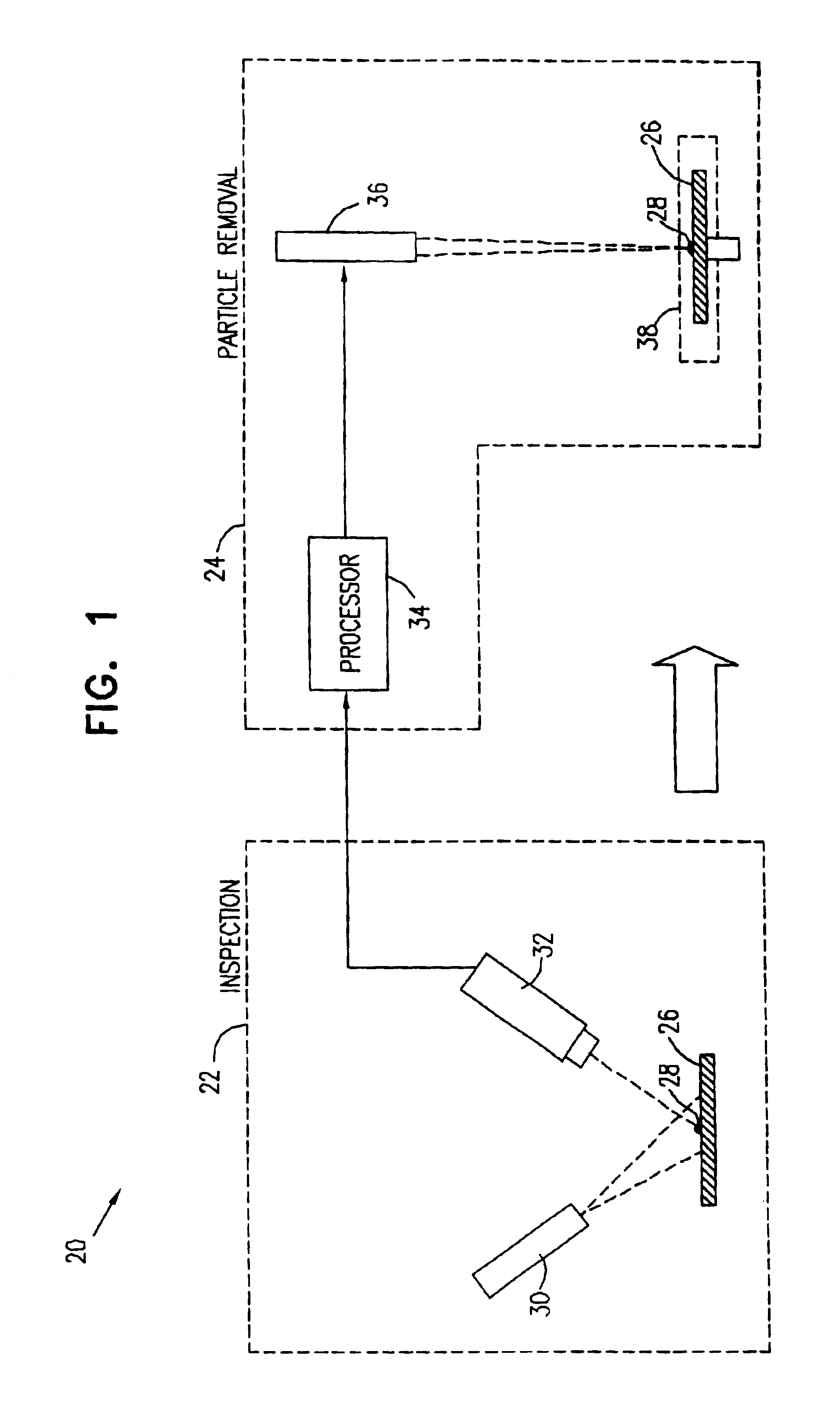
FIG. 1 is a schematic illustration of a system 20 for removal of particles from the surface of a lithographic mask 26, in accordance with an embodiment of the present invention. System 20 is similar in certain aspects to cleaning systems described in U.S. patent application Ser. No. 09 / 869,058 and in PCT patent application PCT / IL99 / 00701, which are assigned to the assignee of the present patent application and are incorporated herein by reference.

System 20 comprises two stations: an inspection station 22 and a particle removal station 24. Typically, stations 22 and 24 are separate entities, as shown in the figure. Inspection station 22 determines the coordinates of contaminant particles 28 on the surface of the mask. The coordinates are passed to a processor 34, which stores the coordinates and transforms them to a coordinate frame of particle removal station 24. Processor 34 has additional functions, as further described with reference to FIG. 2, below. Mask 26 is then transferred ...


PUM

PropertyMeasurementUnit
wavelengthaaaaaaaaaa
wavelengthsaaaaaaaaaa
sizeaaaaaaaaaa

Abstract

Apparatus for semiconductor device fabrication, includes at least one lithography station, which is adapted to project a pattern of radiation from a mask onto a semiconductor wafer. A mask cleaning station is adapted to receive the mask from the at least one lithography station, to clean the mask so as to remove a contaminant therefrom, and so that the cleaned mask may be returned to the at least one lithography station. A robot is adapted to convey the mask between the at least one lithography station and the mask cleaning station. An enclosure contains the at least one lithography station, the mask cleaning station and the robot, so that the mask is conveyed between the at least one lithography station and the mask cleaning station without human contact and without exposure to ambient air.

Description

The present invention relates generally to semiconductor manufacturing processes, and specifically to methods and apparatus for cleaning and handling of lithographic masks used in producing semiconductor devices.BACKGROUND OF INVENTIONAs the trend continues to reduce the size of semiconductor devices, optical lithography using conventional transmission masks, such as chrome on glass (COG) or phase shift (PSM) masks, will no longer suffice as a viable technique for printing advanced devices on semiconductor wafers. Transmission lithography has been extended to ever shorter wavelengths, down to 157 nm in the far ultraviolet (UV), in order to reduce the size of device features. However, the still shorter wavelengths necessary for printing even smaller device structures are readily absorbed in transmission materials. Alternative technological candidates to replace optical lithography include: electron projection lithography (EPL) and an all-reflective technology called extreme ultra-vio...

Claims


Application Information

Patent Timeline
Patent Type & Authority Patents(United States)
IPC IPC(8): H01L21/00G03F1/82
CPCG03F1/82H01L21/67225H01L21/67017
Inventor YOGEV, DAVID
Owner APPL MATERIALS ISRAEL LTD
Why Eureka
Try Eureka