Optical transducers of high sensitivity

a transducer and optical technology, applied in the field of optical transducers of high sensitivity, can solve the problems of relative low sensitivity and achieve the effect of increasing sensitivity

Inactive Publication Date: 2004-12-14
PHONE OR
View PDF4 Cites 31 Cited by
  • Summary
  • Abstract
  • Description
  • Claims
  • Application Information

AI Technical Summary

Benefits of technology

An object of the present invention is to provide an optical transducer which utilizes substantially more of the light generated by the light source within it, and thereby is capable of providing increased sensitivity.
As will be described more particularly below, such an optical transducer utilizes a substantially higher percentage of the light generated by the light source within it, and therefore is capable of providing higher sensitivity.
As will be described below, optical transducers can be constructed in accordance with the foregoing features to provide relatively high sensitivity to displacements of the displaceable member (e.g., deformations of the deformable membrane) as well as high degree of sturdiness enabling such optical transducers to withstand rough handling.

Problems solved by technology

As indicated earlier, one of the drawbacks of the prior art optical transducer illustrated in FIG. 1 is that it utilizes a relatively small part of the light generated by the light source 3, and therefore has relatively low sensitivity.

Method used


Image

  • Optical transducers of high sensitivity
  • Optical transducers of high sensitivity
  • Optical transducers of high sensitivity

Examples


Embodiment Construction

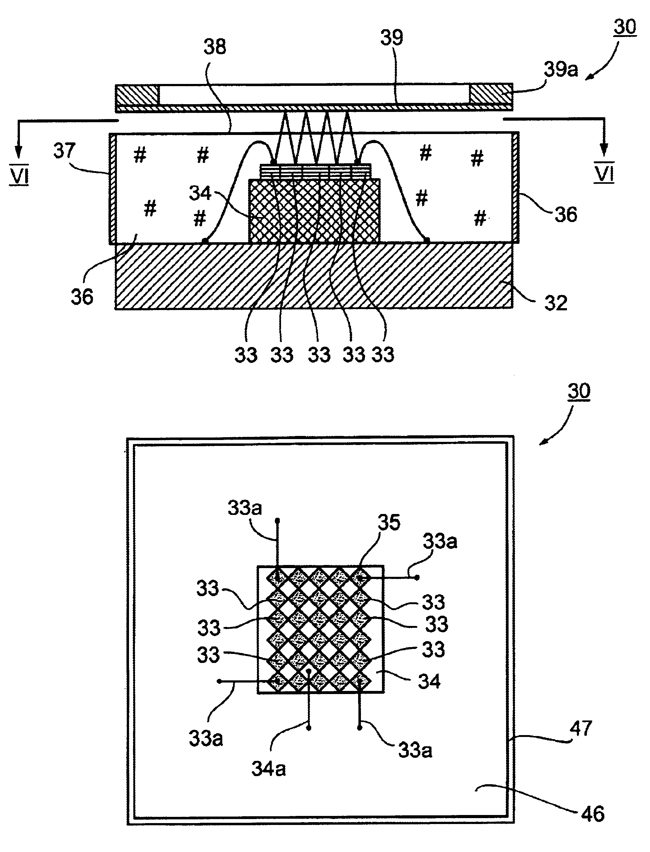
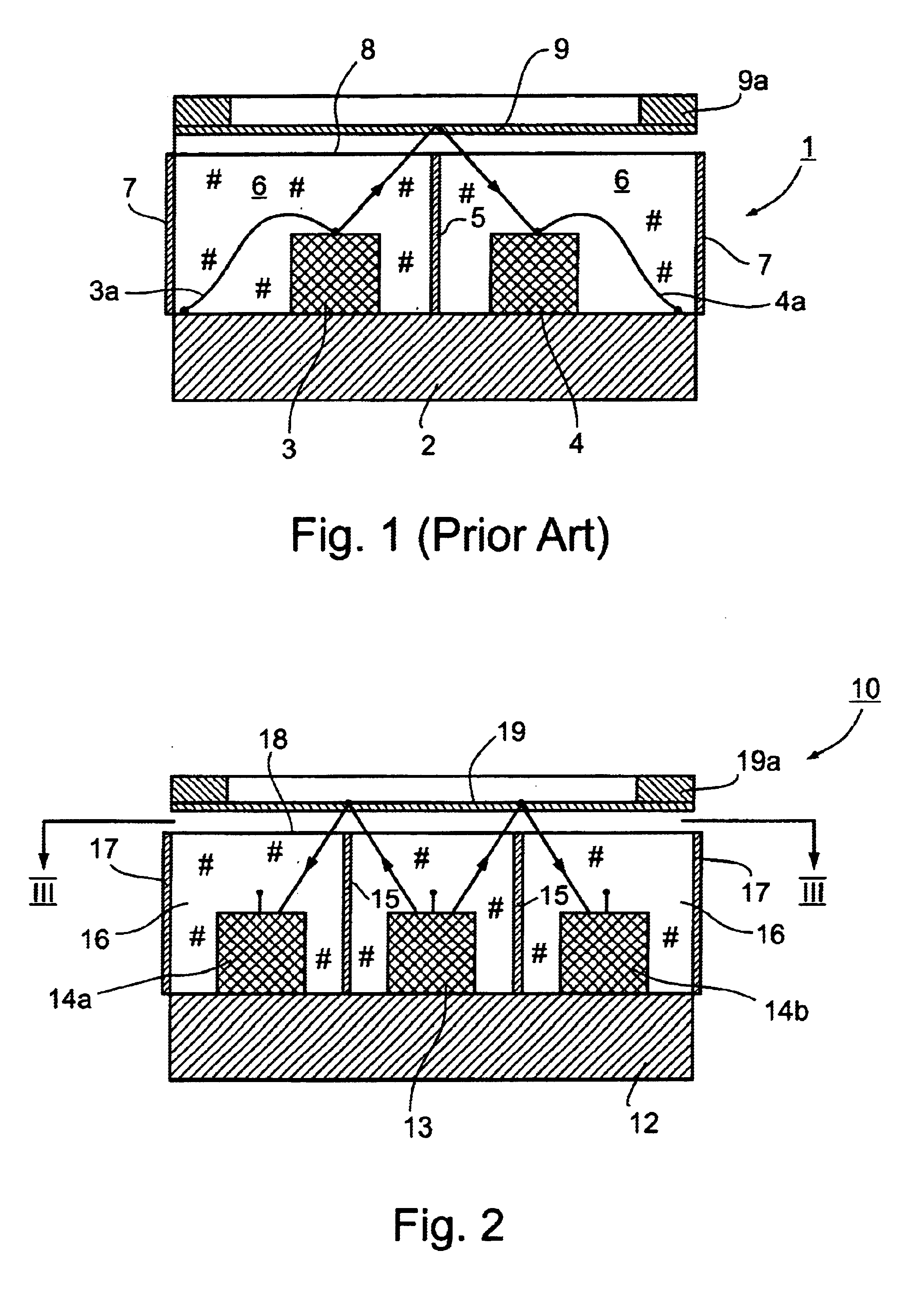
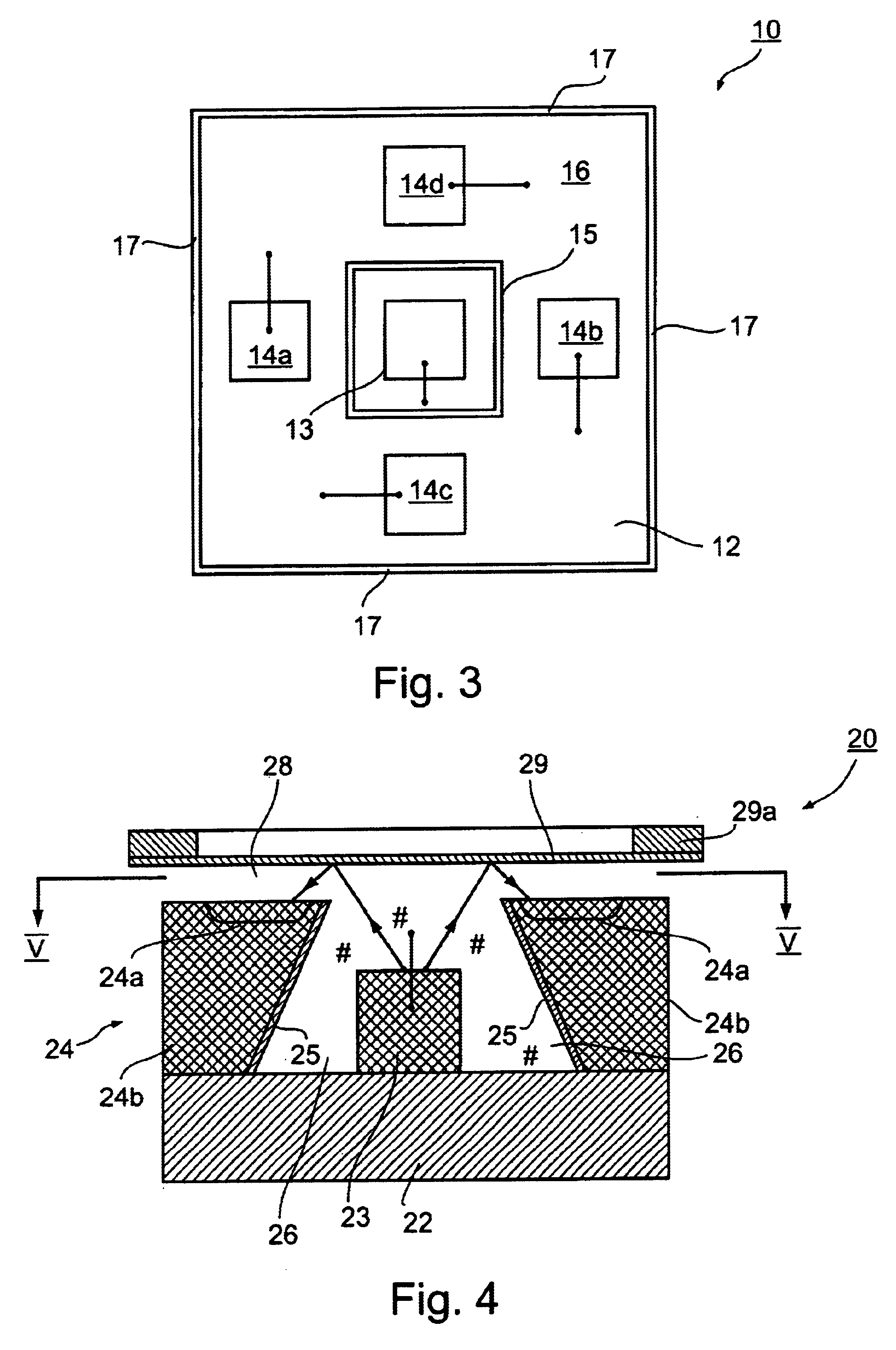
The optical transducer illustrated in FIGS. 2 and 3, and therein generally designated 10, includes a base member in the form of a printed circuit board (PCB) 12, carrying on one face a light source 13 and a light detector in the form of an array of four discrete light detector elements 14a-14d located on all four sides of the light source 13 so as to substantially surround the light source. The illustrated optical transducer further includes light shielding means in the form of a light-blocking layer 15 around the light source 13 such as to shield all the light detector elements 14a-14d from direct exposure to the light source 13. The light source 13, light detector elements 14a-14d, and light-blocking layer 15, are all embedded in a transparent plastic potting material 16. The outer surface of the transparent plastic potting material 16 includes a light-blocking layer 17 to block the exit of light from the light source 13 externally of the optical transducer, and also to block the ...


PUM


Abstract

An optical transducer includes a base member, a light source carried on a face of the base member, a light detector carried on the face of the base member, a displaceable member overlying and spaced from the light source and light detector and effective to reflect light from the light source to the light detector, and light shielding means effective to shield the light detector from exposure to the light source except for the light reflected by the displaceable member from the light source to the light detector. The light detector is configured to substantially surround the light source such as to receive light emitted in substantially all directions from the light source for reflection to the light detector by the displaceable member.

Description

FIELD AND BACKGROUND OF THE INVENTIONThe present invention relates to optical transducers (sometimes referred to as optical sensors,) which utilize optical means for sensing mechanical displacements, such as movements of a body or deformation of a membrane, and converting them to electrical signals. The invention also relates to methods of making such optical transducers. The invention is particularly useful in making optical microphones for converting sound into electrical signals and is therefore described below especially with respect to this application.Optical transducers of this type are described, for example, in U.S. Pat. Nos. 5,771,091; 5,969,838; 6,091,497; and 6,239,865, the contents of which patents are incorporated herein by reference.Such optical transducers generally include an optical unit containing a light source, a laterally spaced light detector, an optical shield between the light source and light detector, and a displaceable member aligned with the optical wind...

Claims


Application Information

Patent Timeline
Patent Type & Authority Patents(United States)
IPC IPC(8): H04R23/00
CPCH04R23/008
Inventor PARITSKY, ALEXANDERKOTS, ALEXANDER
Owner PHONE OR
Why Eureka
Try Eureka