Image display apparatus having voltage application structure

a voltage application and display apparatus technology, applied in the manufacture of electric discharge tubes/lamps, tubes with screens, discharge tubes luminescnet screens, etc., can solve the problems of increased weight, difficult control of the area to which anode potential is applied, and fear of discharging

Inactive Publication Date: 2004-12-14
CANON KK
View PDF13 Cites 19 Cited by
  • Summary
  • Abstract
  • Description
  • Claims
  • Application Information

AI Technical Summary

Problems solved by technology

However, in the case where the depths of the display apparatuses are increased, there occur problems such as enlarged installation spaces and increased weights thereof, which has led to a strong and earnest desire to realize a flat type display apparatus whose thickness and weight are reduced.
We have found, as a result of earnest studies, a problem that it is difficult to perform the control of an area to which an anode potential is applied, in the case where a potential is supplied to an anode electrode through an elastic body like in JP 2000-195449 A and JP 05-114372 A described above.
This changing of the application area of the anode potential causes various problems such as (1) changing of the trajectory of an electron beam emitted from an electron-emitting device in the vicinity of the anode potential application area and (2) induction of accidental discharging within a panel.
We also have found that a high-voltage terminal for supplying a potential to an anode electrode of an anode substrate is led to the outside using an opening established in a cathode substrate, so that a potential on a surface (surface of the cathode substrate exposed to the air) on a side opposite to a surface forming a vacuum container of the cathode substrate becomes unstable and this may bring about accidental discharging or the like.
The atmosphere on the periphery of the opening on the surface of the cathode substrate on the atmosphere side is the air, so that there is a fear that discharging occurs under such a state where a high voltage is applied.
In particular, in the case of a flat panel display, a drive circuit of a display apparatus, a vacuum container holding structure that connects a vacuum container to an enclosure, and the like are arranged adjacent to each other around the surface on a side opposite to the vacuum container forming surface of a cathode substrate, so that there is a fear that accidental discharging is induced between the high-voltage terminal and another member.
Also, there is another problem described below in the case of a structure shown in FIG. 10 described above.
As a result, there is an increased possibility of leakage because a plurality of sealed portions exist, which makes it impossible to obtain a voltage application structure with high hermetic reliability.
As a result, the process of producing the display apparatus becomes complicated and the costs rise.

Method used


Image

  • Image display apparatus having voltage application structure
  • Image display apparatus having voltage application structure
  • Image display apparatus having voltage application structure

Examples


embodiments

(First Embodiment)

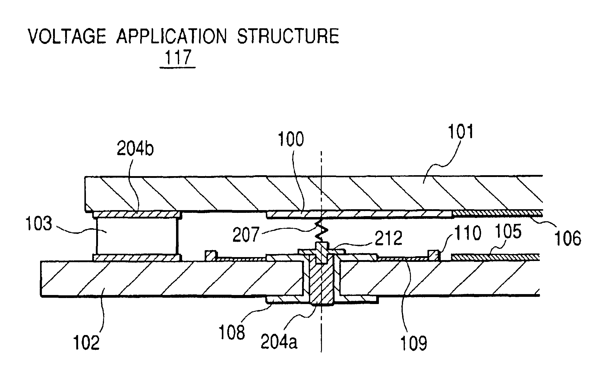
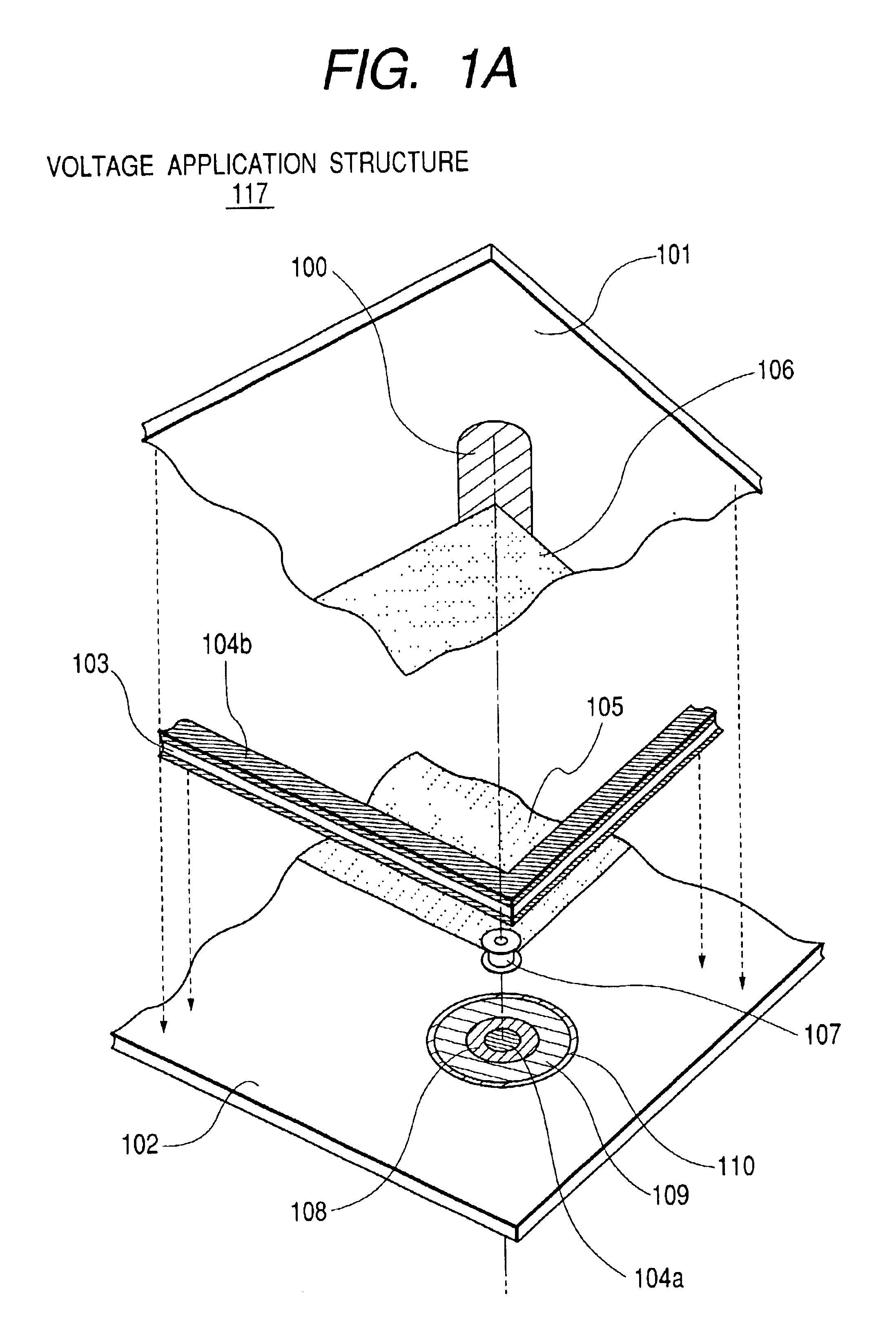
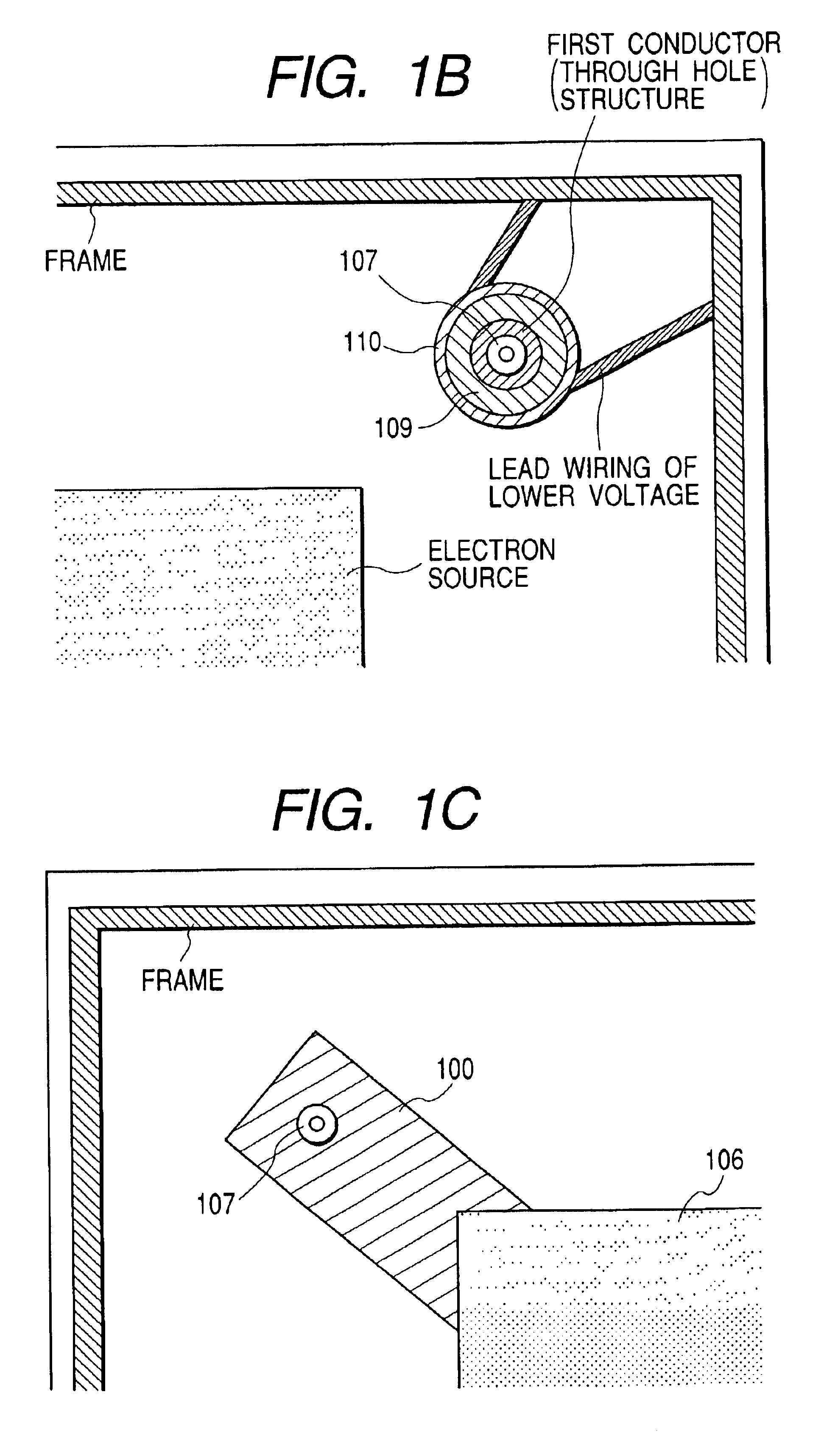
FIGS. 1A to 1C are each a disassembled perspective view of a first embodiment of the voltage application structure 117 of the present invention and a display apparatus using this voltage application structure. Also, FIG. 2 is an assembled sectional view of the first embodiment of the voltage application structure of the present invention and the display apparatus using this voltage application structure. Further, FIG. 4 shows the outline of the voltage application structure and the display apparatus using this voltage application structure shown in FIGS. 1A to 1C and 2. Note that FIG. 4 is a drawing viewed from a side (atmosphere side of the rear plate) opposite to a display portion (not shown) of the display apparatus (the enclosure is omitted in part for ease of explanation and there is shown the rear plate atmosphere side of the display panel).

When the display panel 113 of this embodiment is to be produced, first, a face plate 101, on whose surface an anode elec...

second embodiment

(Second Embodiment)

FIG. 6 is a disassembled perspective view of the second embodiment of the voltage application structure of the present invention and a display apparatus using this voltage application structure. Note that, a disassembled perspective view of the voltage application structure of the present invention and a display apparatus using this voltage application structure is the same as the one in FIG. 1A in the first embodiment. Also, a schematic view of the voltage application structure of the present invention and a display apparatus using this voltage application structure is the same as the one in FIG. 4 in the first embodiment.

Accordingly, there will be described in detail the elastic structure 207 that is a feature differenct from the first embodiment. Note that as to the reference numerals in FIG. 6, the same reference numerals are given to the same construction elements in FIG. 1. Also, other construction elements that are similar to those in FIG. 1 will be describ...

third embodiment

(Third Embodiment)

FIG. 7 is a disassembled perspective view of the third embodiment of the voltage application structure of the present invention and a display apparatus using this voltage application structure. Also, FIG. 8 is an assembled sectional view of the voltage application structure of the present invention and the display apparatus using this voltage application structure. Note that, a schematic view of the voltage application structure of the present invention and a display apparatus using this voltage application structure is the same as the one in FIG. 4 in the first and the second embodiments.

Accordingly, the elastic structure will be described below, which is a feature different between the preceding embodiments and this embodiment. The elastic structure 307 is placed between the through hole structure 108 on the rear plate 102 and the face plate 101. Note that the elastic structure 307 is constructed so as to be substantially axially symmetrical about a center axis a...


PUM


Abstract

To provide a voltage application structure that is electrically stable and a display apparatus using the voltage application structure, while reducing the size, thickness, and cost of the display apparatus. A through hole structure is formed in the vicinity of a cylindrical hole established in a rear plate in advance. The through hole structure is electrically connected to lead wiring led to the outside from an anode electrode through a conductive elastic structure. A voltage to the anode electrode is applied to the through hole structure on the atmosphere side, and thus the voltage is applied to the anode electrode through the vacuum side of the through hole structure, the elastic structure, and the lead wiring. Vacuum hermeticity is maintained by filling the hole of the through hole structure with frit. Also, low-voltage wiring that is connected to the ground and regulates a potential is arranged around the through hole structure.

Description

1. Field of the InventionThe present invention relates to a voltage application structure used for a display of a television receiver, a computer, or the like, a message board that displays characters or images, or the like. The present invention also relates to a display apparatus using this voltage application structure.2. Related Background ArtIn recent years, there have widely been used color cathode-ray tubes (CRTs) as display apparatuses. The driving principle of these CRTs is a method with which electron beams from cathodes are deflected to have phosphors of screens emit light. This means that the display apparatuses are required to have depths corresponding to their screen sizes.However, in the case where the depths of the display apparatuses are increased, there occur problems such as enlarged installation spaces and increased weights thereof, which has led to a strong and earnest desire to realize a flat type display apparatus whose thickness and weight are reduced.As exam...

Claims


Application Information

Patent Timeline
Patent Type & Authority Patents(United States)
IPC IPC(8): H01J29/00H01J29/92H01J31/12
CPCH01J29/92
Inventor KAMIGUCHI, KINYA
Owner CANON KK
Why Eureka
Try Eureka