Auto-detection between referenceless and reference clock mode of operation

a clock mode and reference clock technology, applied in the field of data communication systems, can solve the problems of fewer pins available, not being available to allocate at all, and adding both cost and design complexity to the system in which a clock and data recovery circuit resides

Inactive Publication Date: 2004-12-14
SKYWORKS SOLUTIONS INC
View PDF14 Cites 52 Cited by
  • Summary
  • Abstract
  • Description
  • Claims
  • Application Information

AI Technical Summary

Problems solved by technology

The requirement for a reference clock (generally differential) adds both cost and design complexity to the system in which a clock and data recovery circuit resides.
Unfortunately, integrated circuit pins are a valuable resource for many integrated circuit devices and allocating two of such pins for a reference clock select function

Method used


Image

  • Auto-detection between referenceless and reference clock mode of operation
  • Auto-detection between referenceless and reference clock mode of operation
  • Auto-detection between referenceless and reference clock mode of operation

Examples


Embodiment Construction

)

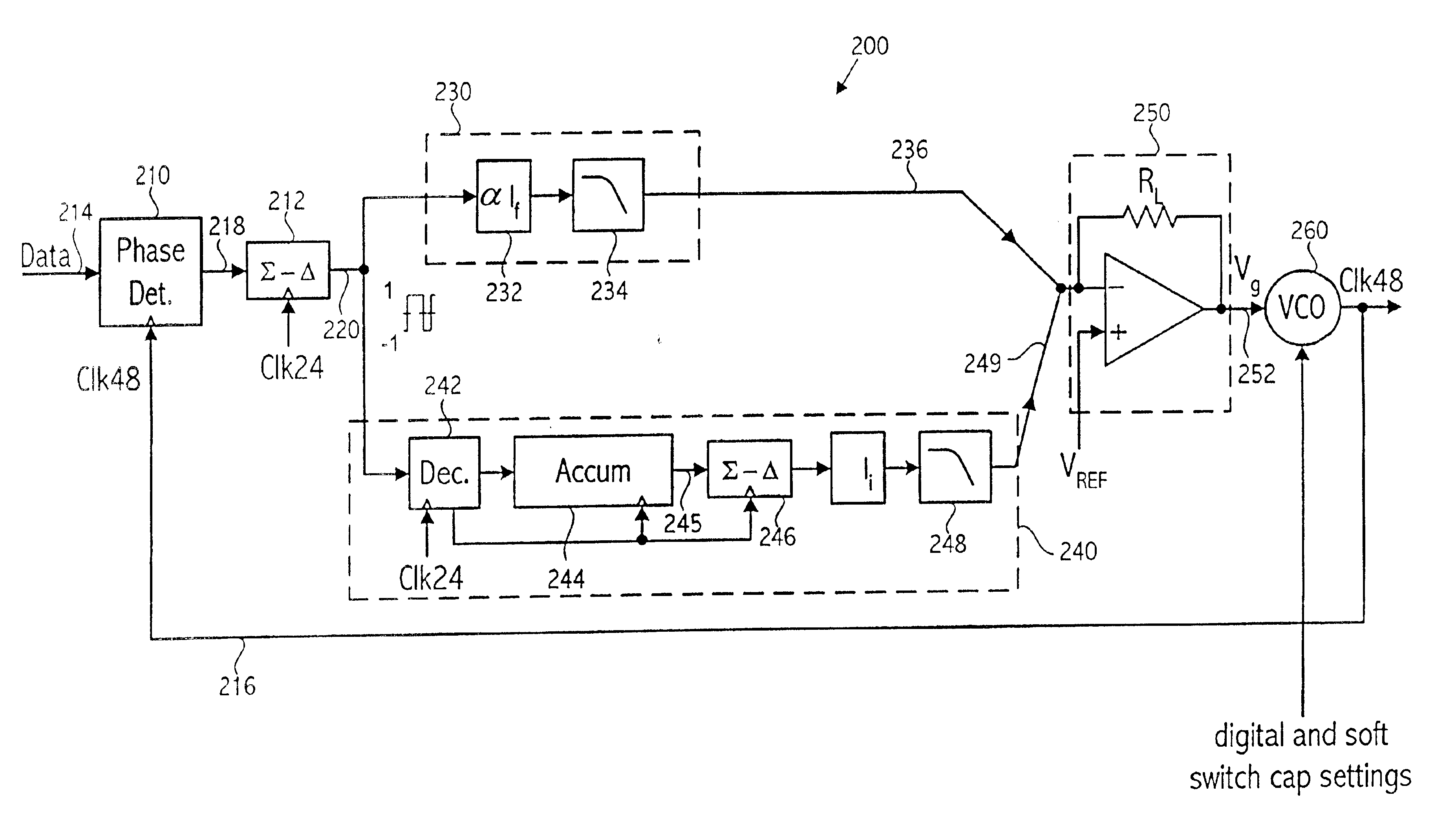
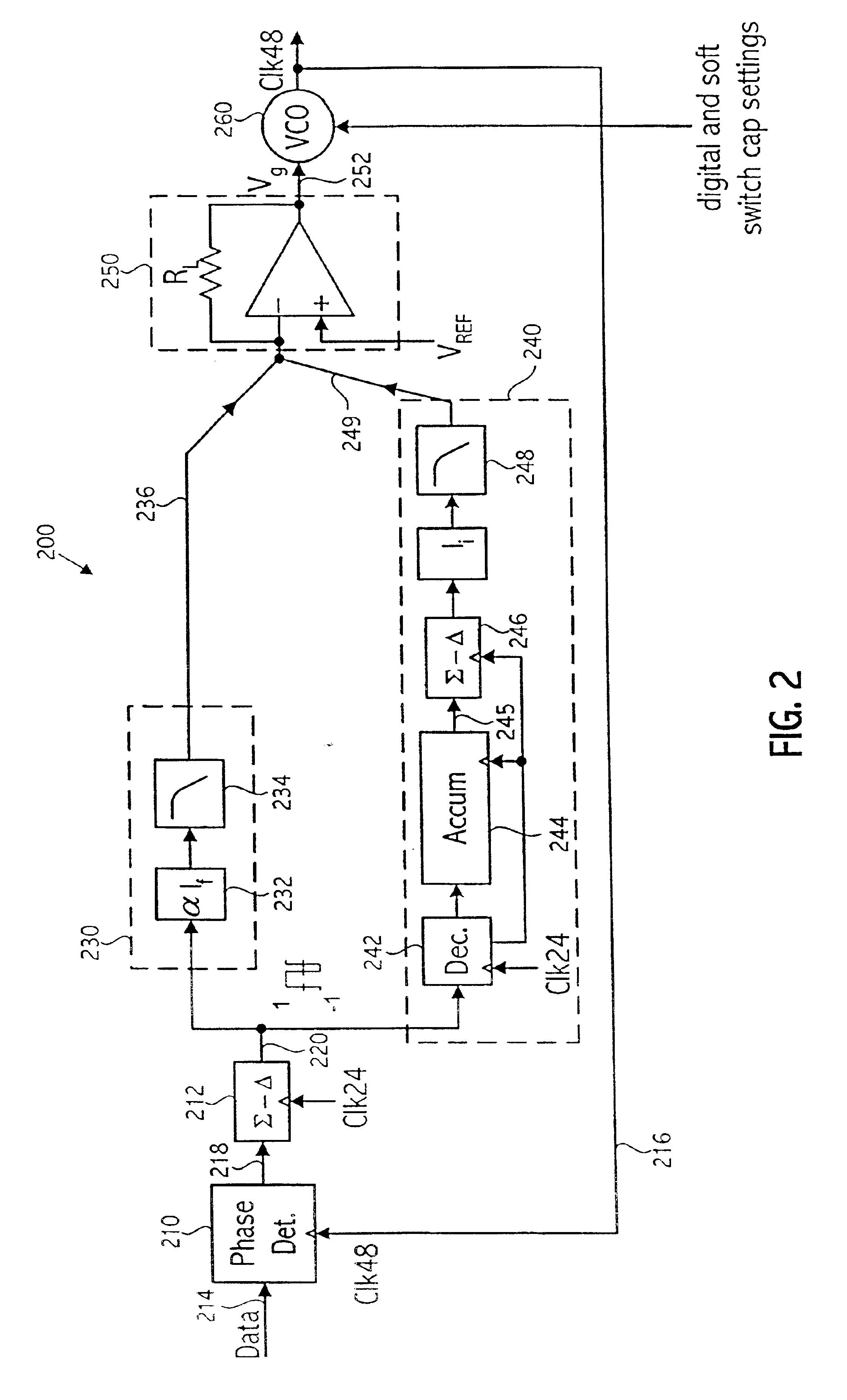
In one embodiment, the invention provides an integrated circuit that provides both referenceless mode of operation in which the timing of an input data stream is recovered without the use of a reference clock, and reference clock mode of operation in which more traditional clock and data recovery techniques are utilized. Further, the embodiment provides not only both modes of operation but an ability to determine which mode of operation is appropriate based on the signal present on the input terminal supplying the reference clock. The input terminal may receive a reference clock (having one of a number of possible frequencies), or the input terminal, in one embodiment is tied to a fixed voltage level, e.g., ground to indicate that no reference clock is being supplied and the integrated circuit should operate in referenceless mode of operation. Before a detailed description is provided for detecting the appropriate mode of operation, a detailed description of referenceless mode of o...


PUM


Abstract

An internal frequency reference, such as a VCO used in a PLL, having a free-running frequency fairly well controlled within a predictable range, is used to determine which of two possible modes of operation, a referenceless or reference clock mode of operation, is used based on a detected frequency of an externally-provided frequency reference signal. The frequency is detected without any additional externally provided signal to indicate the mode of operation or the frequency of the reference clock. If the frequency detection circuit detects a frequency below a predetermined threshold, referenceless mode of operation is indicated. Otherwise, reference clock mode of operation is indicated. In referenceless mode of operation such operations as frequency acquisition and lock detect are performed without the use of a reference clock. In reference clock mode the reference clock is used for such operations as frequency acquisition and lock detect.

Description

1. Field of the InventionThe present invention relates to data communication systems and more particularly to use of an externally provided reference clock by circuits used in acquisition of a timing signal associated with the data communication2. Description of the Related ArtCommunication systems frequently transmit data in which the clock is embedded in the data stream rather than sent as a separate signal. When the data stream is received, a clock and data recovery circuit recovers the embedded clock and retimes the received data to the recovered clock. Traditionally, a phase-locked loop (PLL) has been used to perform the clock recovery operation. FIG. 1 shows a block diagram of a traditional PLL configured for a clock and data recovery application. The phase-locked loop 100 includes a phase detector 102, which receives the input data signal conveyed on node 104 and also receives the VCO output clock signal conveyed on node 106 from the voltage controlled oscillator (VCO) 108. T...

Claims


Application Information

Patent Timeline
IPC IPC(8): H03L7/087H03L7/093H03L7/091H03L7/095H03L7/085H03L7/08H04L7/033H04L7/00
CPCH03L7/085H03L7/087H03L7/091H04L7/033H03L7/095H03L7/093H04L7/0004
Inventor PASTORELLO, DOUGLAS F.PERROTT, MICHAEL H.
Owner SKYWORKS SOLUTIONS INC
Why Eureka
Try Eureka