Stop and start control apparatus of internal combustion engine

a control apparatus and internal combustion engine technology, applied in the direction of electric control, engine starters, machines/engines, etc., can solve the problems of deterioration of emission, failure of stop control, and likely emission deterioration

Active Publication Date: 2004-12-28
TOYOTA JIDOSHA KK
View PDF10 Cites 95 Cited by
  • Summary
  • Abstract
  • Description
  • Claims
  • Application Information

AI Technical Summary

Problems solved by technology

In this situation, since the crankshaft is rotated by the cranking operation of the starter, the fuel supplied in the combustion chamber of the cylinder is discharged through an exhaust port without being burned, which causes the problem of deterioration of emission.
However, when the fuel which is thus supplied to the cylinder in advance is discharged without being combusted, deterioration of emission is likely to occur.
Another example thereof is that the stop control fails and the engine cannot stop at the scheduled engine stop position.
However, when the stop control fails and the cylinder in which the fuel is supplied at the time of stopping the engine passes the exhaust stroke, the unburned fuel is discharged.
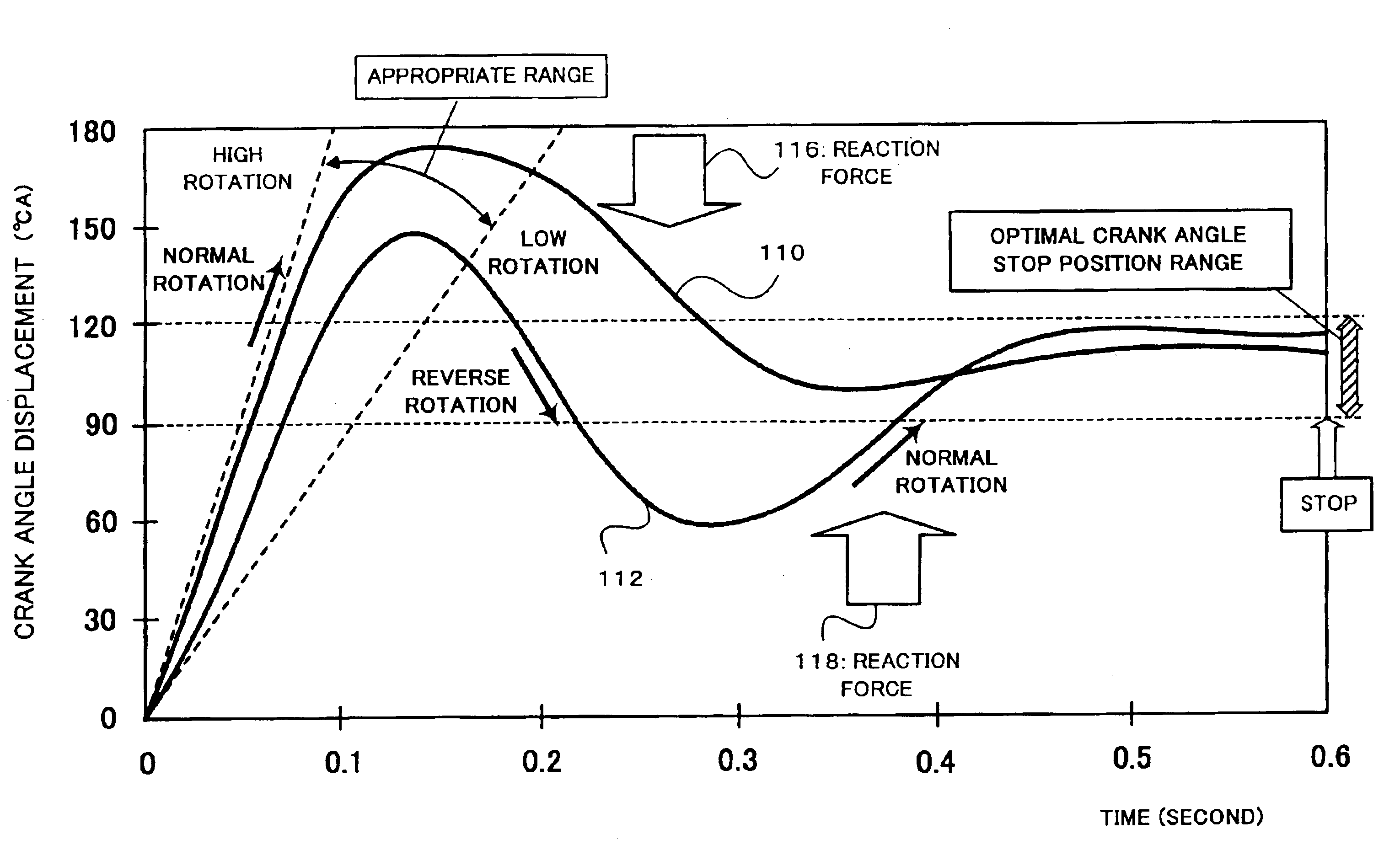
For this reason, with the ordinary stop control method of the vehicle 10, it is difficult to control the crank angle to stop at the optimal crank angle stop position, and the next engine start load becomes large depending on the crank angle stop position when the vehicle actually stops.

Method used


Image

  • Stop and start control apparatus of internal combustion engine
  • Stop and start control apparatus of internal combustion engine
  • Stop and start control apparatus of internal combustion engine

Examples


application example

of the First Example

Next, an application example of the first example will be explained. The application example of the first example is a control to suppress the vibration, occurring when the unburned fuel is combusted in the first example, by using the motor generator 3 so that the drives feels less uncomfortable feeling.

In the above-described first example, the engine is temporarily started by igniting and exploding the unburned fuel sealed in each of the combustion chambers of the #3 cylinder which is the stop time compression stroke cylinder and the #1 cylinder which is the stop time expansion stroke cylinder, and the unburned fuel is prevented from being discharged to the atmosphere through the exhaust port 38. However, a vibration may occur to the vehicle 10 due to the explosion energy, and when it is large, it gives uncomfortable feeling to the driver.

Therefore, in order to suppress the vibration, in this example, the rotation driving force from the motor generator 3 is give...

second example

In the second example, after the unburned fuel is introduced and sealed in each of the combustion chambers of the #1 cylinder which is the stop time expansion stroke cylinder and the #3 cylinder which is the stop time compression stroke cylinder, if it is determined that the engine stop control to the aforesaid each stop control position is impossible, the exhaust valve of each of the cylinders are closed at predetermined timings to prevent the unburned fuel being discharged from the exhaust port 38. Thus, deterioration of the emission is avoided. This example is based on the premise that the engine employs the function of controlling opening and closing of the exhaust valve at an arbitrary timing.

The second example will be explained with reference to FIG. 13 and FIG. 14. FIG. 13 shows a stroke chart showing a state of each cylinder just before the engine stop, and a time chart corresponding to the stroke chart. FIG. 13 shows a case that the engine stop control to the stop control p...

third example

In the third example, after the unburned fuel is sealed in each of the combustion chambers of the #1 cylinder which is the stop time expansion stroke cylinder and the #3 cylinder which is the stop time compression stroke cylinder, if the engine stop control cannot be executed as scheduled and it is estimated that the unburned fuel is discharged through the exhaust valves, the ignition processing is executed to combust the unburned fuel. As a result, even if the engine stop control fails, it is possible to prevent the unburned fuel from being discharged into the air, and hence to prevent deterioration of emission. The third example is especially effective for the engine which cannot freely control the opening and closing of the exhaust valve at arbitrary timings.

The third example will be explained with reference to FIG. 15 and FIG. 16. FIG. 15 shows a stroke chart showing a state of each cylinder just before the engine stop, and a time chart corresponding to the stroke chart. The cha...


PUM


Abstract

A stop and start control apparatus of an internal combustion engine prevents fuel supplied in a specific cylinder at the time of stopping the engine from being discharged in an unburned state. When an ignition switch is turned off in a state that the unburned fuel is sealed in the combustion chamber of a specific cylinder during idling stop, the unburned fuel is combusted to prevent the unburned fuel from being discharged. The vibration occurring at that time can be suppressed by rotating the motor generator in the counter direction to the rotation direction of the crankshaft. After the unburned fuel is sealed in the combustion chamber of the specific cylinder, if it is estimated that the unburned fuel is discharged, the exhaust valve corresponding to the specific cylinder is closed at the predetermined timing, or the unburned fuel is combusted, whereby the unburned fuel is prevented from being discharged. Thus, deterioration of emission can be avoided.

Description

1. Field of the InventionThe present invention relates to a stop and start control apparatus of an internal combustion engine, and relates to an discharge prevention technique of an unburned fuel, which prevents fuel supplied to a specific cylinder from being discharged in an unburned state at the time of stopping the internal combustion engine.2. Description of the Related ArtRecently, there is known an engine stop and start control apparatus for automatically stopping an internal combustion engine (hereinafter, also referred to as "engine") when the vehicle stops and for automatically restarting the engine to start the vehicle when an instruction to start is given in the stopped state, in order to reduce a fuel consumption amount and exhaust gas during idling, from the viewpoint of environmental conservation, resources and energy saving or the like. This control is also called "idling stop" or the like.It is known that, when the idling stop is automatically carried out, it is effe...

Claims


Application Information

Patent Timeline
Patent Type & Authority Patents(United States)
IPC IPC(8): F02N17/00F02N11/08F02D41/04F02N15/00F02D13/02F02D17/00F02D29/02F02D41/00F02D41/06F02D41/36F02D43/00F02D45/00F02N11/04F02N99/00
CPCF02N11/0814F02N99/006F02D41/0087F02D41/042F02D41/065F02D2041/0095Y02T10/48F02N19/005F02N2019/008F02D2250/24Y02T10/40
Inventor KATAOKA, KENJIKUSAKA, YASUSHI
Owner TOYOTA JIDOSHA KK
Why Eureka
Try Eureka