Electric machine with low eddy current losses

Inactive Publication Date: 2004-12-28
ABB (SCHWEIZ) AG
View PDF10 Cites 12 Cited by
  • Summary
  • Abstract
  • Description
  • Claims
  • Application Information

AI Technical Summary

Problems solved by technology

This stray or leak flux involves some inconveniences.
Firstly, the main flux is reduced therethrough, which results in a somewhat lower power of the electric machine.
Furthermore, the stray flux will generate eddy currents in the strands, which results in heat generation and a demand of cooling the cables, which normally takes place indirectly by cooling the sheet package surrounding them.
However, this means that

Method used


Image

  • Electric machine with low eddy current losses
  • Electric machine with low eddy current losses
  • Electric machine with low eddy current losses

Examples


Embodiment Construction

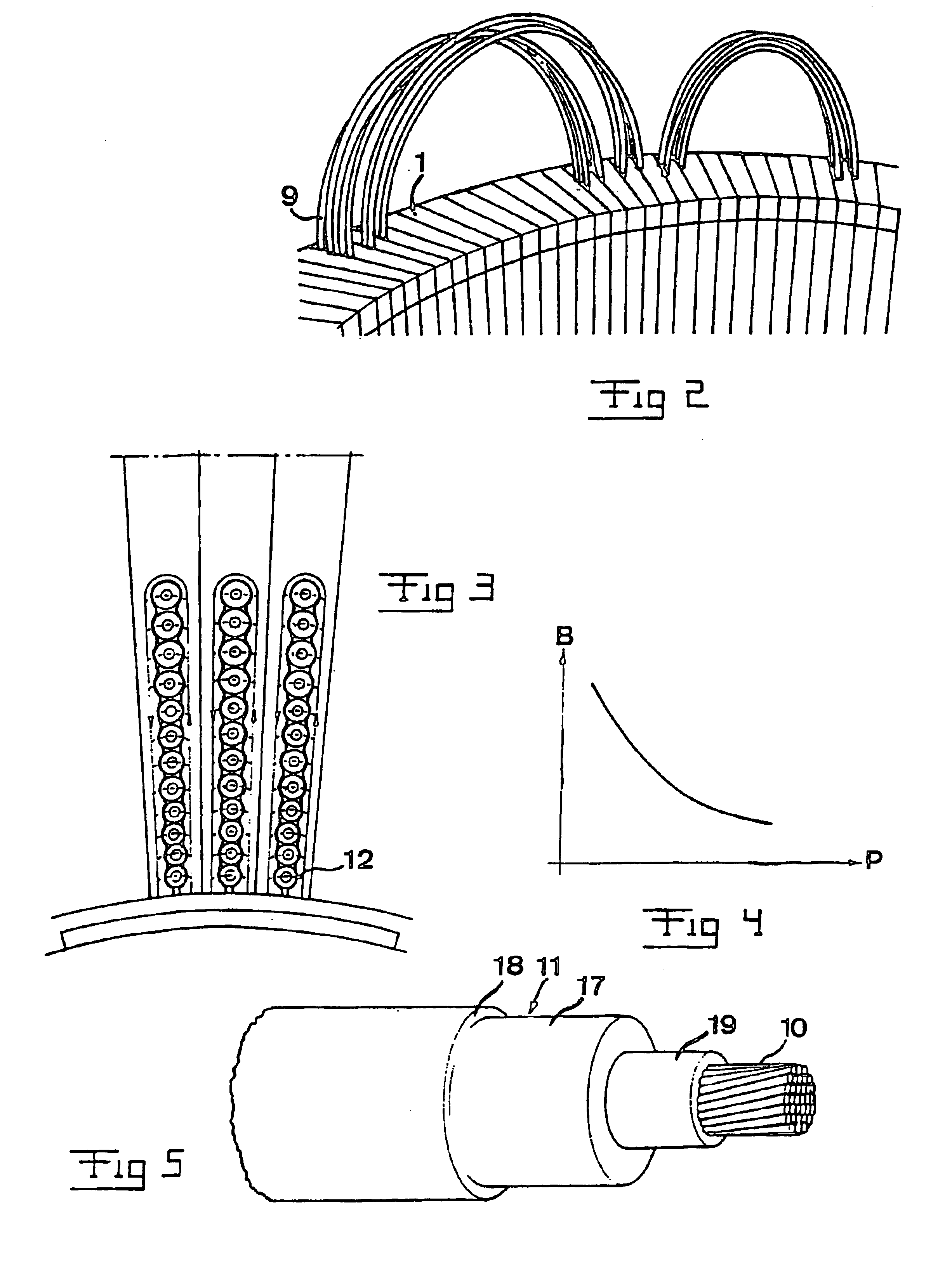
It is firstly illustrated in FIG. 2 how the cables 9 are arranged in the slots in the element 1 by threading them thereinto. All cables are not yet in place here.

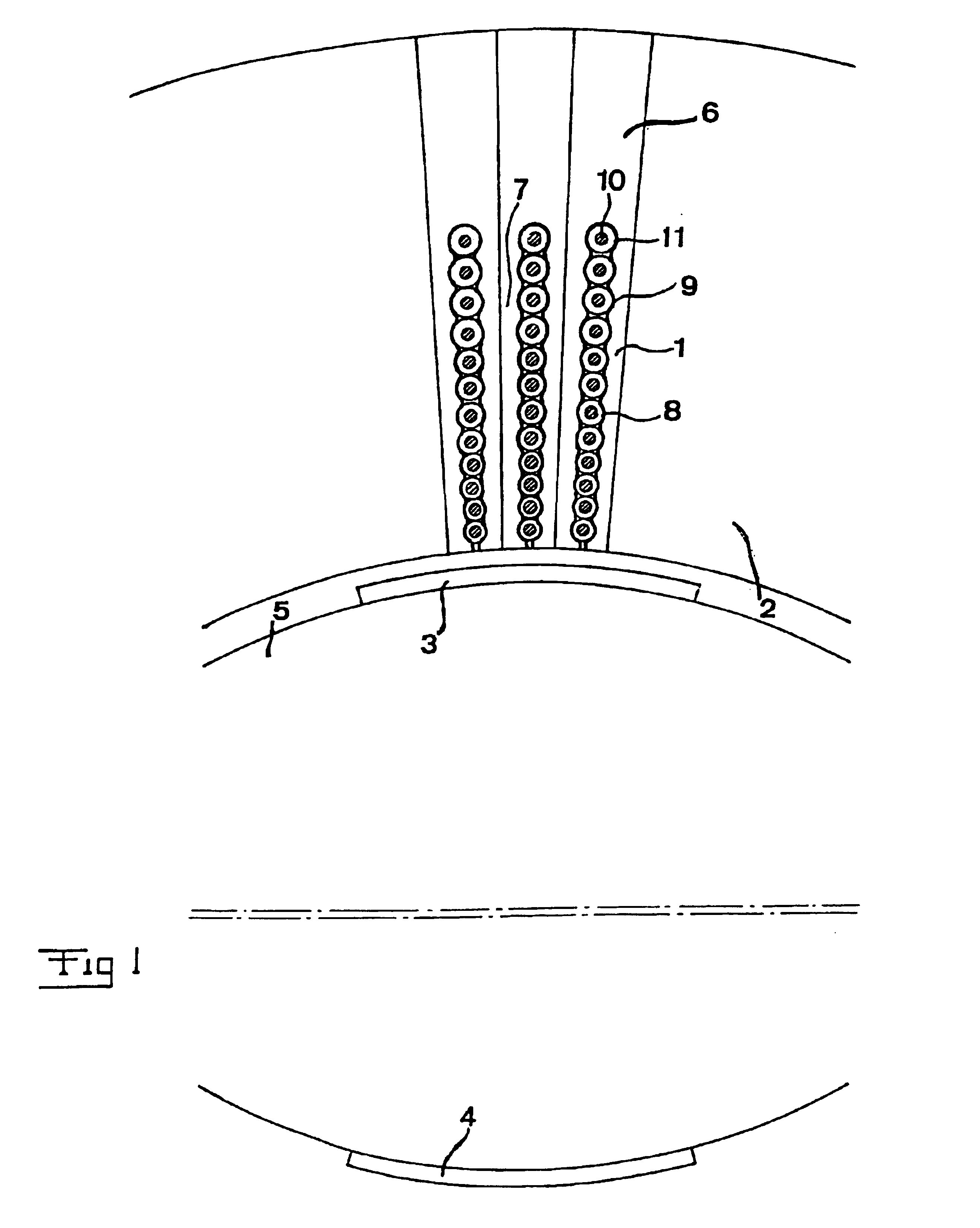
It is illustrated in FIG. 4 how the leak flux B decreases for each position P of the cable 9 away from the rotor, i.e. with increasing distance from the rotor. The explanation thereto is that the relationship between the leak flux path and the alternative path for the magnetic flux through the element 1 around the cable layer increases continuously.

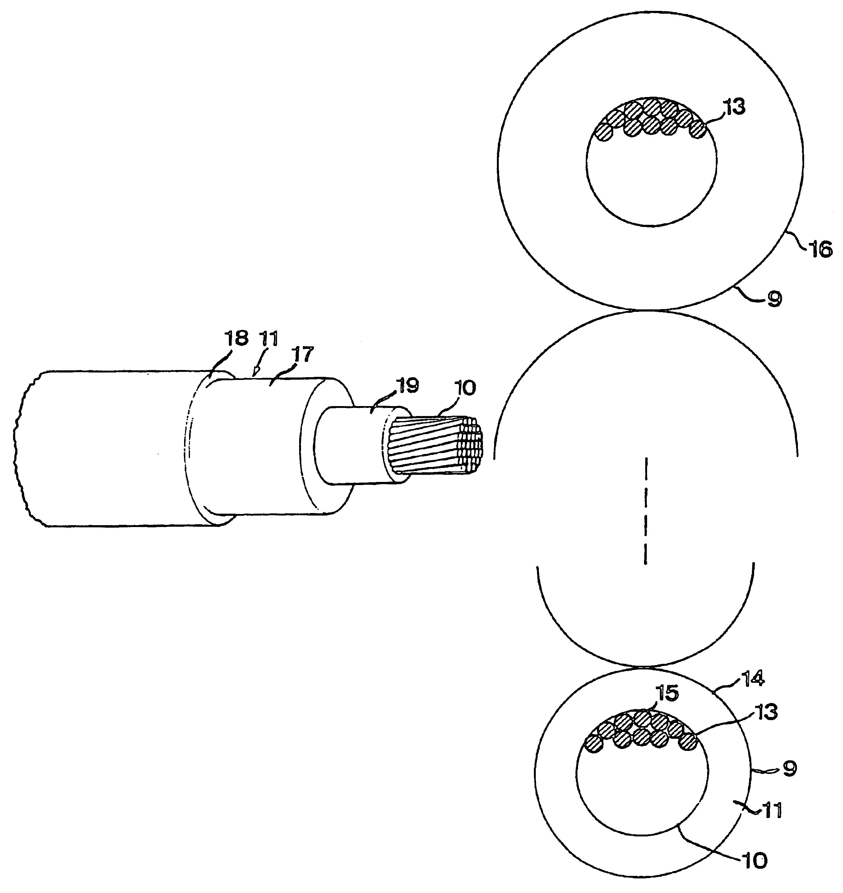
It is illustrated in FIG. 6 how this understanding has resulted in a first preferred embodiment of the invention, in which the strands 13 (the entire conductor 10 is of course filled by strands, even if the figures show other things for the sake of simplicity) of the cable layer 14 located closest to the rotor are electrically insulated with respect to each other through a thin insulating layer 15 surrounding each strand, which may be of a conventional insulating lacquer. This is...


PUM


Abstract

A rotating electric machine having a magnetic circuit which in one of the parts of a rotor and a stator of the machine comprises an element (1) having a slot for a winding of layers (14, 16) of cables (9) extending substantially axially and arranged substantially radially outside each other, said cables comprising an inner conductor (10) comprising a plurality of strands (13) and an insulation (11) arranged outside thereof, has a larger share of strands of the cables closest to the other part of the rotor and the stator electrically insulated (15) with respect to each other than in the cables in the cable layer (16) most far away from said other part.

Description

FIELD OF THE INVENTION AND PRIOR ARTThe present invention relates to a rotating electric machine having a magnetic circuit which in one of the parts of a rotor and a stator of the machine comprises an element having a slot for a winding having layers of cables extending substantially axially and arranged substantially radially outside each other, said cables comprising an inner conductor comprising a plurality of strands and an insulation externally thereof.All types of rotating electric machines of the type with winding of a cable are comprised, i.e. such machines in which there is an insulation sheet around the conductor and the conductor is formed by a bundle of strands. All voltage ranges, high voltage as well as intermediate voltage and low voltage are comprised.The element in the magnetic circuit with a slot for the cables may as mentioned be arranged in any of the parts: rotor and stator, of the electric machine. "Slot" is here to be given a broad sense and does not necessari...

Claims


Application Information

Patent Timeline
IPC IPC(8): H02K3/00H02K3/34H02K3/40H02K3/42H02K3/32H02K3/12
CPCH02K3/34H02K3/40H02K3/42Y10S174/28H02K2203/15Y10S174/20
Inventor LEIJON, MATS
Owner ABB (SCHWEIZ) AG
Why Eureka
Try Eureka