
Vibrating fishing rod

Inactive Publication Date: 2005-01-04
NATURE VISION
View PDF53 Cites 22 Cited by
  • Summary
  • Abstract
  • Description
  • Claims
  • Application Information

AI Technical Summary

Benefits of technology

It is a further object of the invention to provide a switch having timing control over the vibrator whereby a fisherman can select desired periods of operation.

Problems solved by technology

Although active jigging actions can be productive with active, feeding fish, a continuing problem is enticing a neutral or generally inactive fish into striking a presented bait.

Method used


Image

  • Vibrating fishing rod
  • Vibrating fishing rod
  • Vibrating fishing rod

Examples


Embodiment Construction

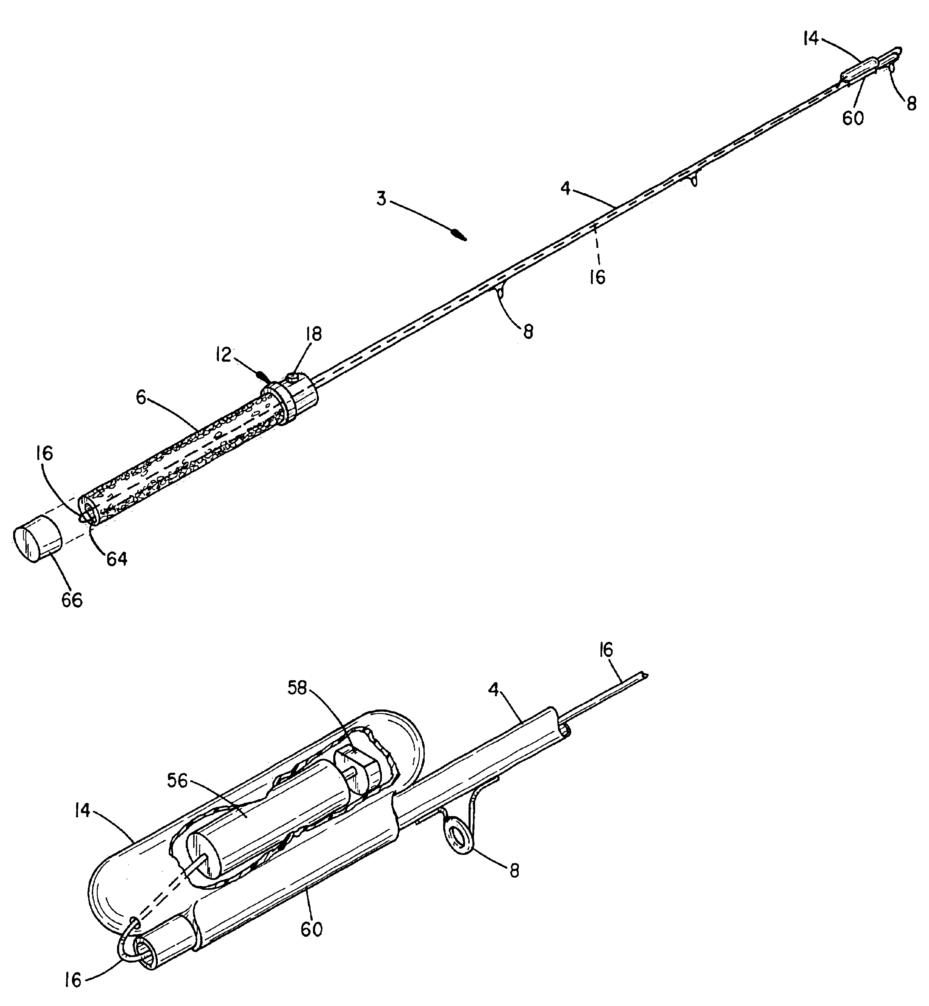
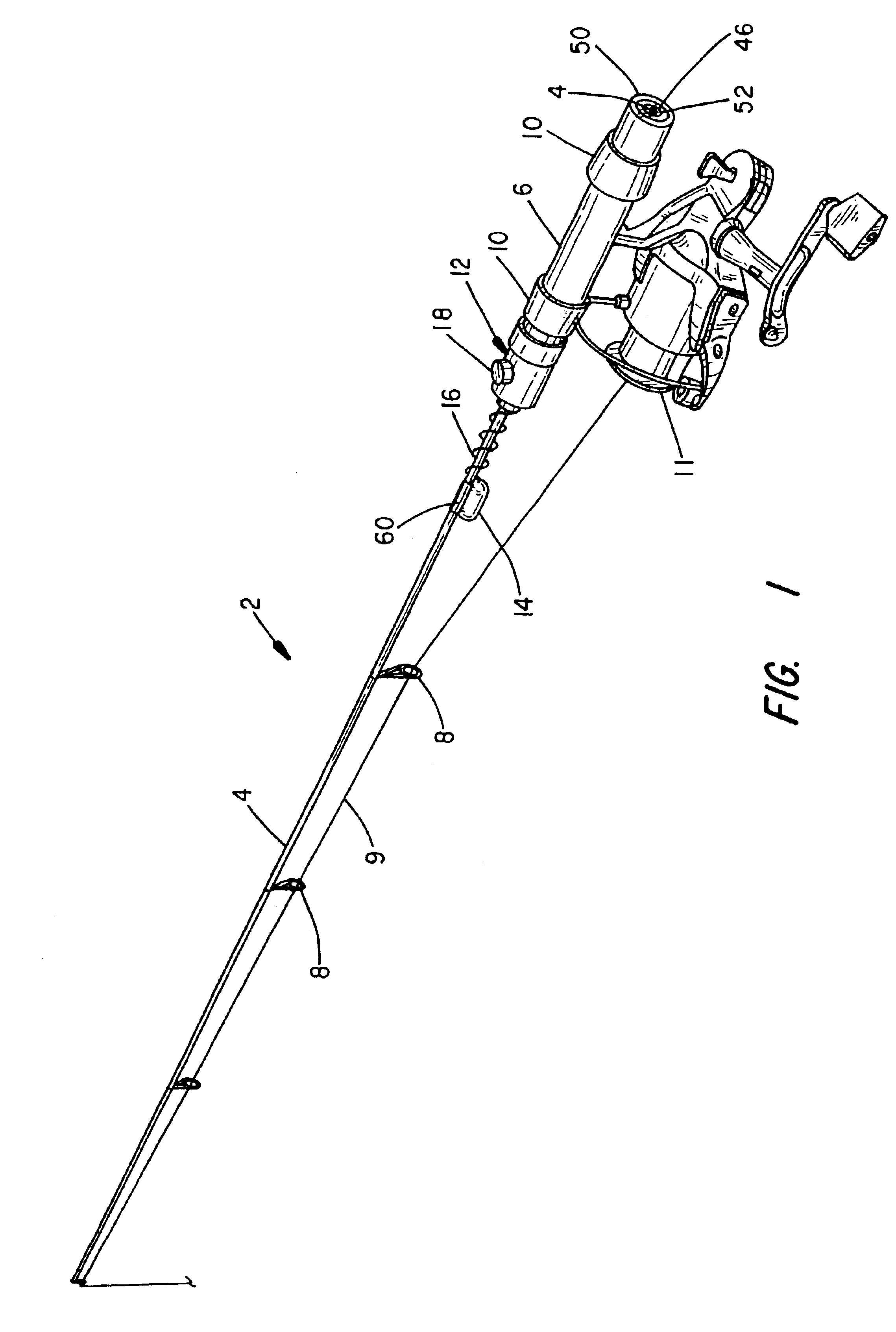
Referring to FIG. 1, a perspective drawing is shown to a typical ice fishing rod 2. FIG. 5 shows an open water fishing rod. The principal difference between ice rods and open water rods is rod length. Ice fishing rods typically extend 24-inches to 48-inches, whereas open freshwater water rods are much longer and can extend 5-feet to 10-feet. Shore fishing rods (e.g. telescoping poles might extend 15-feet to 20-feet. Saltwater rod length varies depending upon the species and fishing technique (e.g. shore or boat).

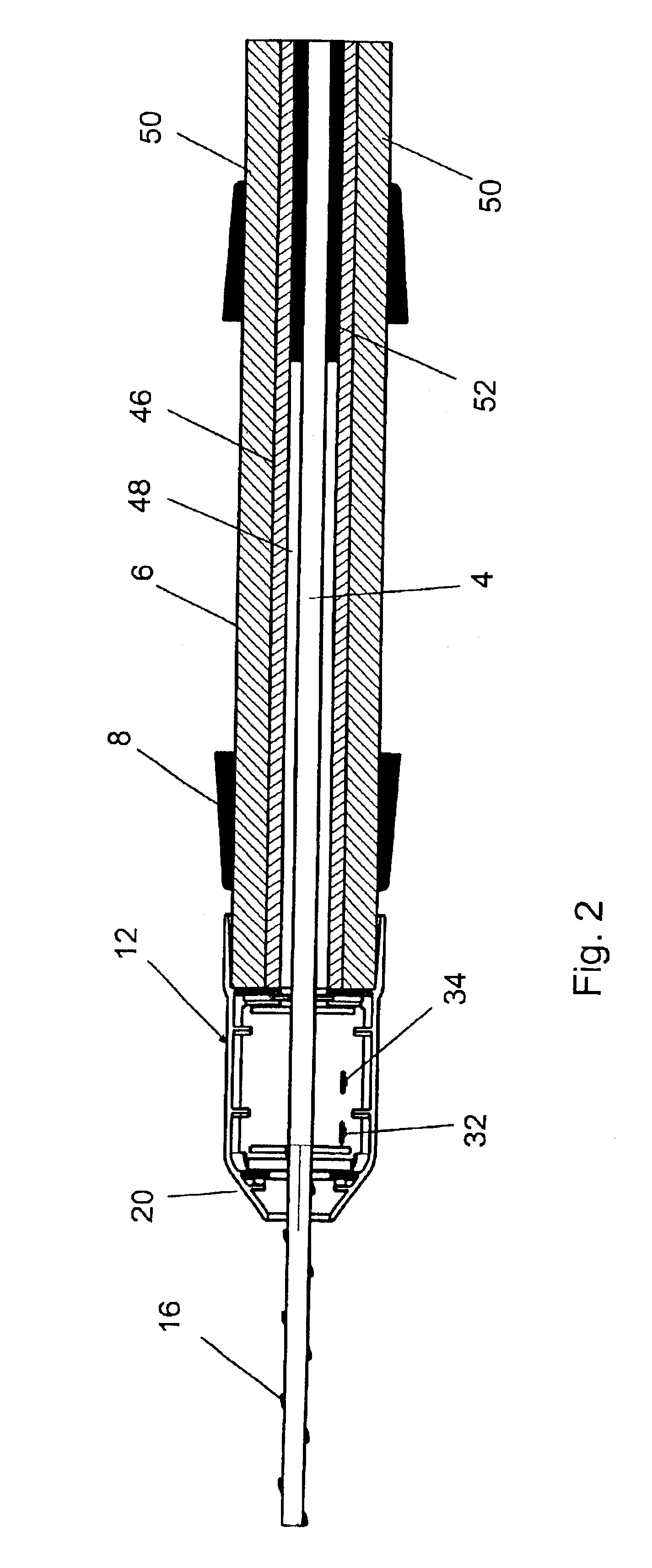
The rod 2, regardless of length, consists of a tapered rod blank 4 that is mounted to a handle 6. The rod blank 4 can be constructed of a variety of conventional fiberglass, graphite and composite materials. A number of line guides 8 are secured to the blank 4 with windings of wrapped thread that are sealed with an epoxy. A pair of annular rings secure a fishing reel 11 containing a length of fishing line 9 to the handle 6. The reel 11 can vary in construction (e.g. open or ...


PUM


Abstract

A fishing rod having a motorized vibrator secured to a floating rod blank. The rod blank is substantially displaced from the bore of a handle. A ferrule switch mounted to a suspended portion of the handle contains a battery power source that is manipulated as a switch contact. A vibrator includes a motor and eccentric weight and is supported to the rod blank forward of the handle and responsively vibrates the rod blank for controlled periods and / or frequencies and a supported fishing line and lure.

Description

BACKGROUND OF THE INVENTIONThe present invention relates to fishing rods and, in particular, to a rod blank suspended within a rod handle and having a ferrule switch mounted to the rod handle and a vibrator mounted to the rod blank to induce vibrating movement to a suspend fishing line and lure.A common fishing technique is to jig a rod up and down from several inches to several feet in a preferred sequence to cause a suspended lure to correspondingly rise and fall with a fluttering action that initiates an injured prey species. Such movements attract fish and can induce active or feeding fish to strike. A variety of devices have therefore been developed to support and jig or manipulate a fishing rod up and down, for example U.S. Pat. Nos. 6,401,380; 4,251,939; 4,100,695; 4,020,582.A variety of other devices have been developed to jig or manipulate a fishing line up and down, for example U.S. Pat. Nos. 4,821,948; 4,528,767; 4,420,900; 4,349,978; 4,120,112; 3,981,095; 3,789,534; 3,60...

Claims


Application Information

Patent Timeline
IPC IPC(8): A01K91/06A01K91/00
CPCA01K91/065
Inventor ZERNOV, JEFFREY P
Owner NATURE VISION
Learn More