Photo-catalytic reactor

a photocatalytic reactor and photocatalytic technology, applied in the direction of electrochemical generators, cell components, cell component details, etc., can solve the problems of high purification of fuel, poor performance, loss of efficiency, etc., and achieve the effect of generating useable energy

Active Publication Date: 2006-11-02
THE UNIV COURT OF THE UNIV OF ABERDEEN REGENT WALK
View PDF6 Cites 98 Cited by
  • Summary
  • Abstract
  • Description
  • Claims
  • Application Information

AI Technical Summary

Benefits of technology

[0023] The arrangement of the photocatalyst to receive light may involve an optical path wherein the aforesaid proton-conductive membrane is juxtaposed with further light-conductive materials e.g. so-called “light pipes” to enhance the delivery of light to the photocatalytic surface. Such an arrangement facilitates the presentation of a plurality of photocatalytic cells in a battery or stack preferably of thin (0.3-0.5 mm) cells. Where light pipes are used, cell thickness may increase to approximately 1 mm or more. The light source is preferably natural light (solar energy), but artificial light sources may be also provided. The operation of the invention may be improved by provision of light gathering and intensification optics.
[0041] The fuel cell of this invention can be utilised for any of the proposed uses of a conventional direct oxidation fuel cell, provided that a suitable light source is available. For instance the cells, fuelled by an oxidizable substance, preferably a relatively inexpensive organic liquid such as methanol, can be used to power electrically operated devices. The ability of the photocatalyst types selected for use in this invention to oxidise (thereby consuming, degrading, or destroying) a wide range of organic materials also allows the invention to be used as an energy efficient method of remediating waste streams, such as aqueous waste streams, from industrial processes that contain organic materials. The fuel cell can be fed such a waste stream which will be oxidised at the anode whilst generating electrical energy that can be used to power required equipment such as pumps, or used elsewhere in the event of a surplus being generated. Thereby, two objectives are achievable in that noxious materials are disposed of in an environmentally acceptable manner and, in so doing, useful energy is generated.
[0042] Photocatalytic oxidation of hazardous organic pollutants has been a growing area of environmental technology over the last twenty years. The mineralisation of low molecular weight alcohols and chlorinated alkanes, acetone and the partial oxidation of mycrocystins to less toxic forms in potable waters has been demonstrated, all using TiO2-based catalyst. Conventional photocatalytic oxidation processes in this theme generally utilise photocatalyst slurries. This invention seeks to enhance catalyst efficiency by utilising thin films, as in the area of photoelectrocatalysis and photovoltaics, connected to an external electrical circuit. The prospect of recovering electrical energy from the degradative oxidation of organic pollutants is particularly attractive in terms of sustainability and waste utilisation.

Problems solved by technology

Difficulties encountered in producing a practical direct fuel cell include: Catalyst and electrode design and efficiency, avoiding poisoning and minimising the production of undesirable side products such as carbon monoxide; Efficiency of the cathode, especially if air is used as the oxygen containing gas, the nitrogen present can ‘blanket’ or slow down the transport of the oxygen to the catalyst surface; Fuel ‘cross-over’, i.e. the anode and cathode of the cell are separated by an tonically conductive medium such as a high molecular weight electrolyte or solid proton conducting membrane, but if the fuel can permeate that membrane and be transported from the anode to the cathode then efficiency is lost; and Choice of electrolyte—direct oxidation fuel cells often employ sulphuric acid as the electrolyte but the consequent presence of sulphate ions and sulphur can result in poor performance.
A disadvantage of the known types of fuel cell is that they generally require highly purified fuel to prevent catalyst poisoning.

Method used


Image

  • Photo-catalytic reactor
  • Photo-catalytic reactor
  • Photo-catalytic reactor

Examples


Embodiment Construction

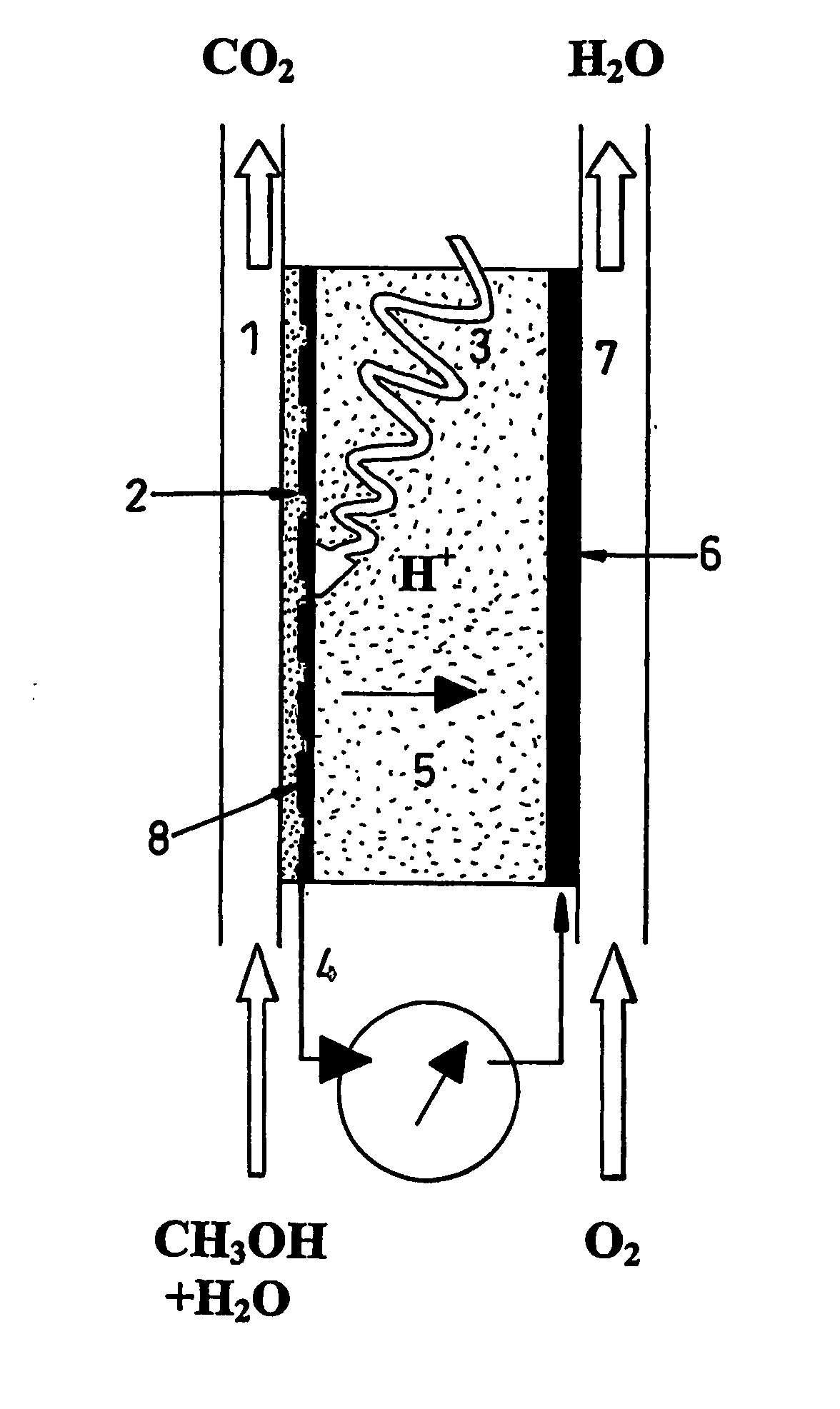
[0056] The fuel cell of the present invention will now be described by way of example in terms of a cell that uses methanol as the fuel, and performs as a photocatalytic reactor wherein the fuel is oxidised at the anode, releasing protons, but it will be understood that other fuels may be adopted, and that organic contaminants in fluids e.g. oil-polluted water can serve as “fuel”.

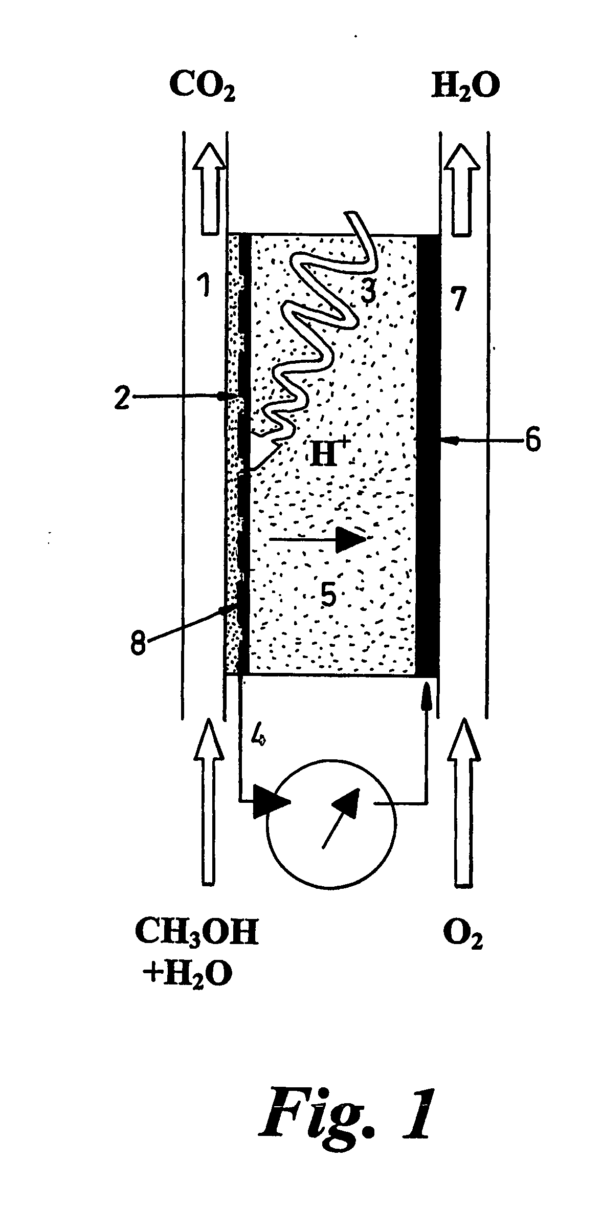
[0057] The fuel cell comprises electrodes and proton-conducting membrane units as illustrated in FIG. 2. Perforated, porous or grid electrodes ensure that charge carriers can transit across all interfaces and that all electrical contacts within the electrochemical cell are continuous so that one external connection to a mesh or foraminated metallic sheet will be sufficient (see FIG. 2), but multiple connections are not excluded. The photocatalyst (1) can be dip-coated or applied by other means onto the previously fabricated proton conducting membrane (PCM) (3) having a platinum, or other electronically con...


PUM

PropertyMeasurementUnit
thicknessaaaaaaaaaa
conductivityaaaaaaaaaa
thickaaaaaaaaaa

Abstract

A photocatalytic reactor, capable of generating an electric current by consumption of a fuel containing organic material, comprises a direct oxidation fuel cell including an anode and a cathode. The anode is a photocatalysis-assisted anode which comprises a photocatalyst on a surface of an electrically-conductive substrate so arranged as to be receptive to light. A light-transmissive proton-conductive membrane is arranged between the anode and the cathode, such that light passes through said membrane as a final stage in the optical path to the photocatalyst. The photocatalyst promotes oxidation of organic material and generates electron-hole pairs. The reactor, configured to support multiple cells in a stacked array, is provided with inlet(s) for introducing said fuel and connector(s) for connection to an external electrical circuit.

Description

FIELD OF THE INVENTION [0001] The present invention generally relates to use of fuel cells, and in particular liquid feed organic fuel cells wherein oxidation of the fuel is achieved by photocatalysis. The invention to be particularly described hereinafter provides an energy efficient photocatalytic reactor. BACKGROUND OF THE INVENTION [0002] Fuel cells are electrochemical cells in which a free energy change resulting from a fuel oxidation reaction is converted into electrical energy. In an organic / air fuel cell an organic material such as methanol or other suitable fuel is oxidised to carbon dioxide at the anode whilst oxygen from air, or oxygen enriched air, or oxygen gas itself, is reduced to water at the cathode. [0003] Two types of organic / air fuel cells are generally known: [0004] 1. An indirect fuel cell in which the organic fuel is catalytically reformed and processed into hydrogen, which is used as the actual fuel for the fuel cell by being oxidised at the anode. [0005] 2. ...

Claims


Application Information

Patent Timeline
Patent Type & Authority Applications(United States)
IPC IPC(8): H01M4/90H01M8/10H01M4/88H01M8/06H01M8/16H01M14/00
CPCH01M8/0606H01M8/1009Y02E60/523H01M14/005H01M8/16Y02E60/527
Inventor MACPHEE, DONALD ELLIOT
Owner THE UNIV COURT OF THE UNIV OF ABERDEEN REGENT WALK
Why Eureka
Try Eureka