Atomic clock for downhole applications

a technology of atomic clocks and downholes, applied in the field of geophysical exploration, can solve the problems of clocks being easily distorted, downhole clocks, and clocks being also susceptible to errors

Inactive Publication Date: 2005-01-04
BAKER HUGHES INC
View PDF17 Cites 28 Cited by
  • Summary
  • Abstract
  • Description
  • Claims
  • Application Information

AI Technical Summary

Problems solved by technology

It is difficult, if not impossible, to explicitly and accurately determine the seismic velocity of formations solely from the surface seismic survey, therefore when a wellbore is drilled in a relatively unexplored area, a borehole seismic receiver is used to make measurements to determine the velocity of the seismic energy within the formations.
This lack of knowledge could cause the planned wellbore trajectory to miss the target entirely.
The downhole clock, in particular, is susceptible to drift caused by substantial changes in temperature found in the downhole environment.
Such clocks are also susceptible to errors caused by shock and vibration during deployment.
The downhole clock drifts out of synchronization with the surface clock, causing unacceptable degradation of the output seismic profile data.
In such applications, the deployment time may be hundreds of hours, exacerbating the problem of clock drift.
Several re-synchronizing techniques have been proposed, however these techniques are not always operationally acceptable and / or successful.

Method used


Image

  • Atomic clock for downhole applications
  • Atomic clock for downhole applications
  • Atomic clock for downhole applications

Examples


Embodiment Construction

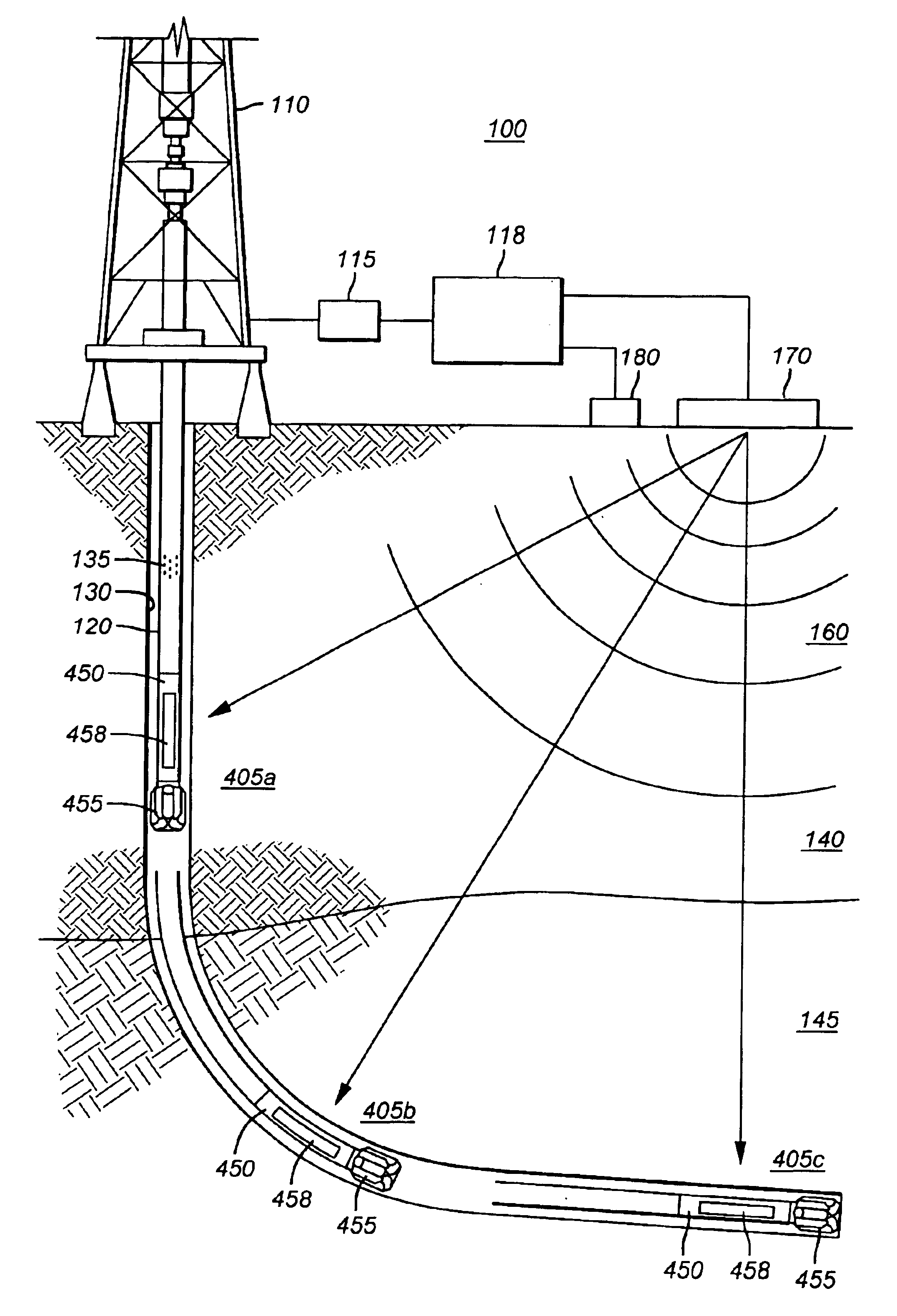
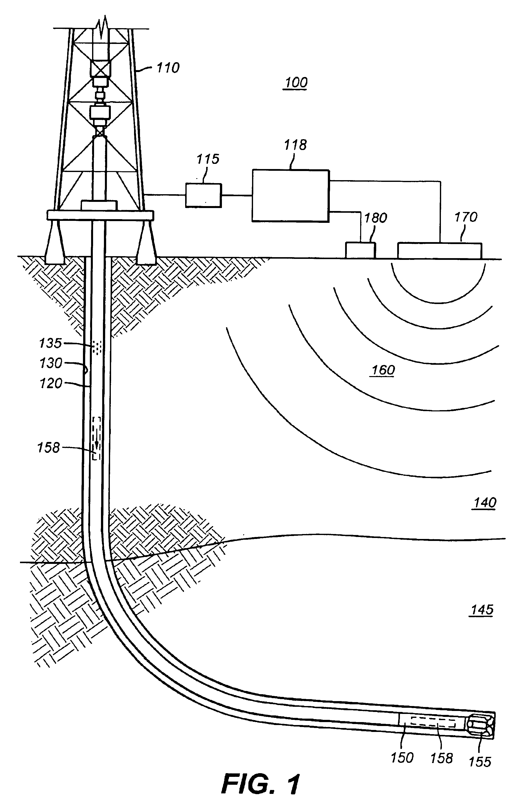
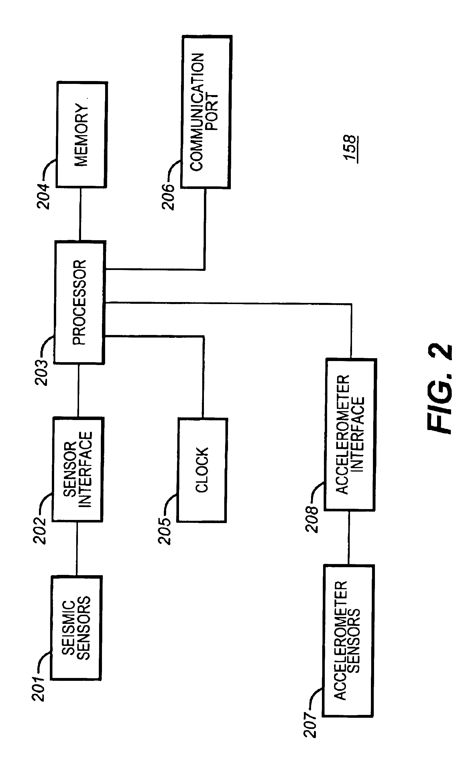
In one embodiment, referring to FIG. 1, a system 100 according to the present invention includes a derrick 110 with an attached tubular member, such as drill string 120. A drill bit 155 creates a wellbore 130 through the surrounding formation 140, which may also include formation boundaries corresponding to, for example, an over-pressurized zone 145. A seismic receiver 158, configured here in a sonde configuration, has appropriate seismic sensors and is inserted into the drill string 120. The seismic receiver 158 may fall by gravity to a landing sub 150 near the drill bit 155. Alternatively, the seismic receiver 158 may be deployed using the drilling fluid 135 to effectively pump the receiver 158 to the landing sub 150. Further alternatively, the receiver 158 may be integrated into any MWD or wireline system configuration in a manner well-known in the art.

The seismic receiver 158 receives seismic signals 160 from a seismic source 170, such as a mechanical vibrator, located at the su...


PUM


Abstract

A system and method for acquiring seismic data are disclosed. The system comprises a controller for causing the generation of a seismic signal, where the controller has a first clock used for time-stamping a record of the generated seismic signal. A seismic receiver is deployed in a wellbore so as to detect the generated seismic signal. An atomic clock is disposed in or with the seismic receiver for time-stamping a record of the detected seismic signal. The atomic clock is synchronized with the first clock prior to being placed downhole.

Description

CROSS-REFERENCE TO RELATED APPLICATIONSNot applicableSTATEMENT REGARDING FEDERALLY SPONSORED RESEARCH OR DEVELOPMENTNot applicableBACKGROUND OF THE INVENTION1. Field of the InventionThe present invention is related to the field of geophysical exploration and more specifically to a system and method for synchronizing downhole and surface-acquired data.2. Description of the Related ArtA seismic receiver typically is deployed in a wellbore for determining the response of the earth to seismic energy in the vicinity of the wellbore, which enables determination of certain characteristics of the earth in the vicinity of the wellbore, such as geological structure and the location of changes in the material properties of the earth which may naturally occur.One of the reasons for using a borehole seismic receiver is for matching various depths within the earth penetrated by the wellbore to specific travel times of seismic energy generated at the earth's surface. In relatively unexplored areas...

Claims


Application Information

Patent Timeline
Patent Type & Authority Patents(United States)
IPC IPC(8): E21B47/12G01V1/46G01V1/16G01V1/40G01V1/42
CPCG01V1/46G01V1/16G01V1/42G04F5/14E21B47/12
Inventor DIFOGGIO, ROCCOREITTINGER, PETER W.
Owner BAKER HUGHES INC
Why Eureka
Try Eureka