Cable end connector having good insulation function

a technology of low-profile cable end connectors and insulation functions, which is applied in the direction of connections, electrical apparatus, printed circuits, etc., can solve the problems of unreliable insulation function between the terminal and the conductive shell, the flexible dielectric member may not be strong enough to securely hold the terminal therein, and the tabs of the terminal of the small cable end connector are too tiny to retain the terminal in the dielectric member, etc., to achieve the effect of reliably insulating the terminal

Inactive Publication Date: 2005-01-04
HON HAI PRECISION IND CO LTD
View PDF8 Cites 24 Cited by
  • Summary
  • Abstract
  • Description
  • Claims
  • Application Information

AI Technical Summary

Benefits of technology

A main object of the present invention is to provide a cable end connecto...

Problems solved by technology

However, because current cable end connector is very small, the tabs of the terminal of the small cable end connector are too tiny to retain the terminal in the dielectric member.
By a relatively large mating force of the header, the terminal tends to be pushed out...

Method used


Image

  • Cable end connector having good insulation function
  • Cable end connector having good insulation function
  • Cable end connector having good insulation function

Examples


Embodiment Construction

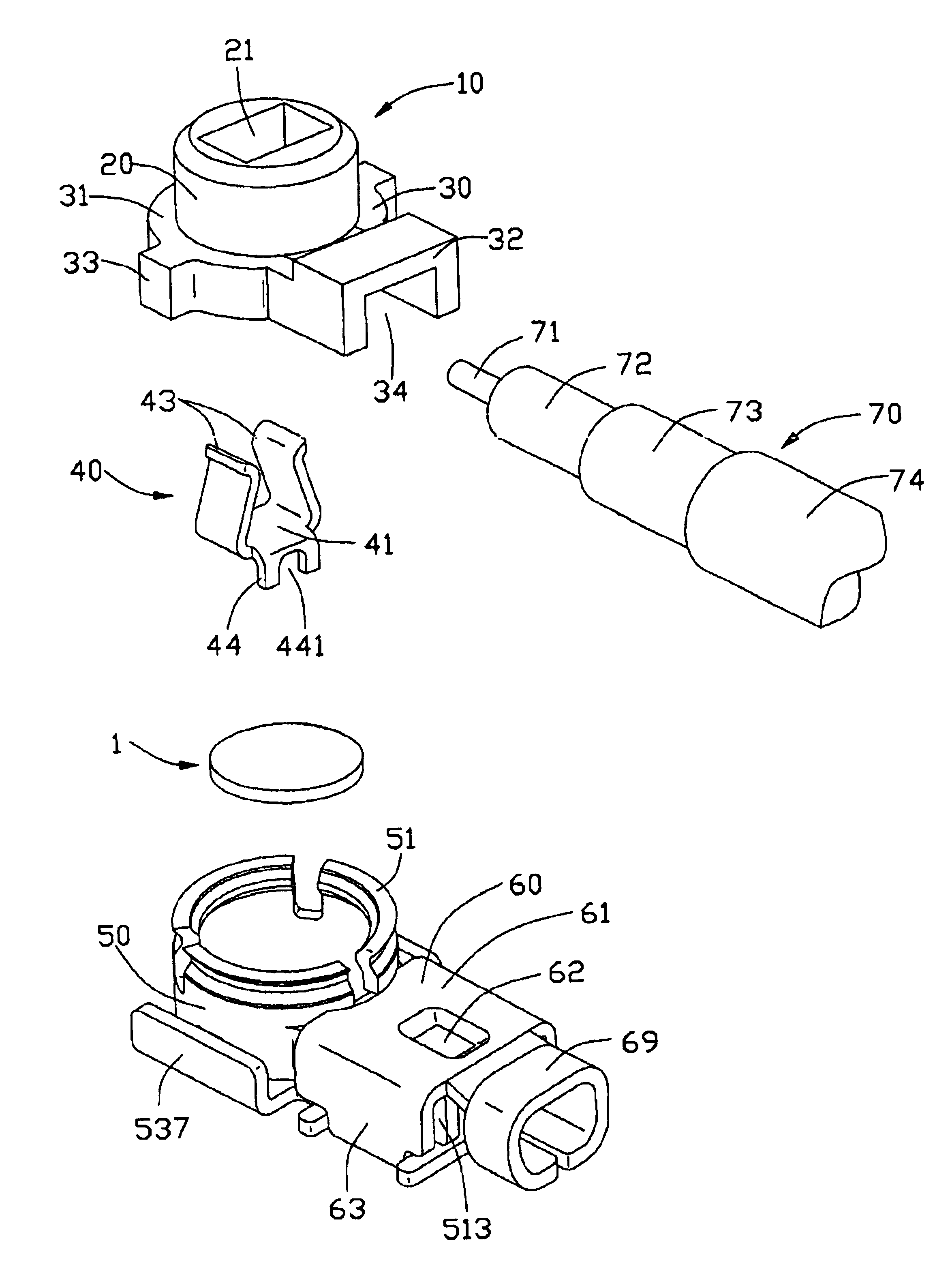
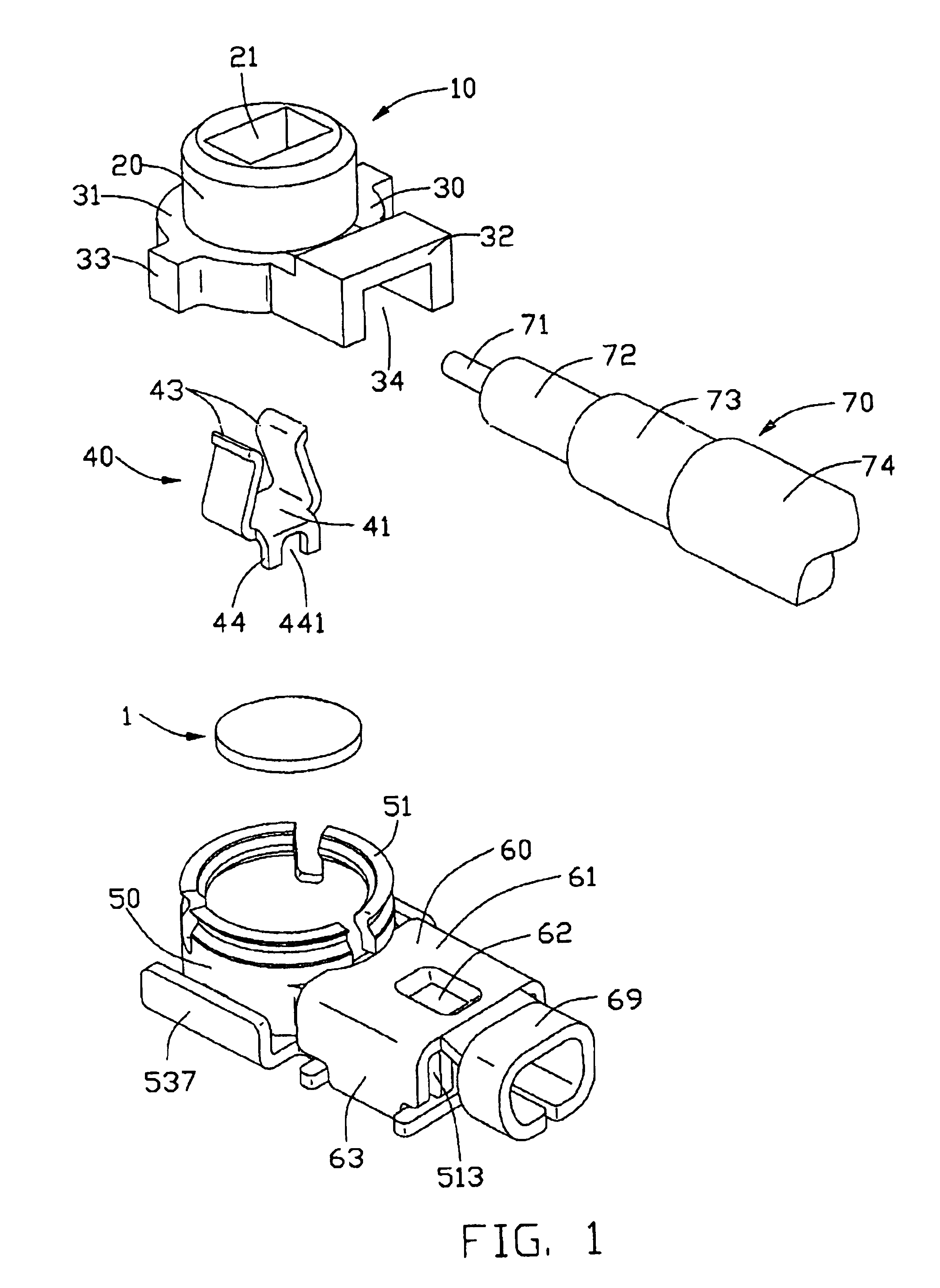
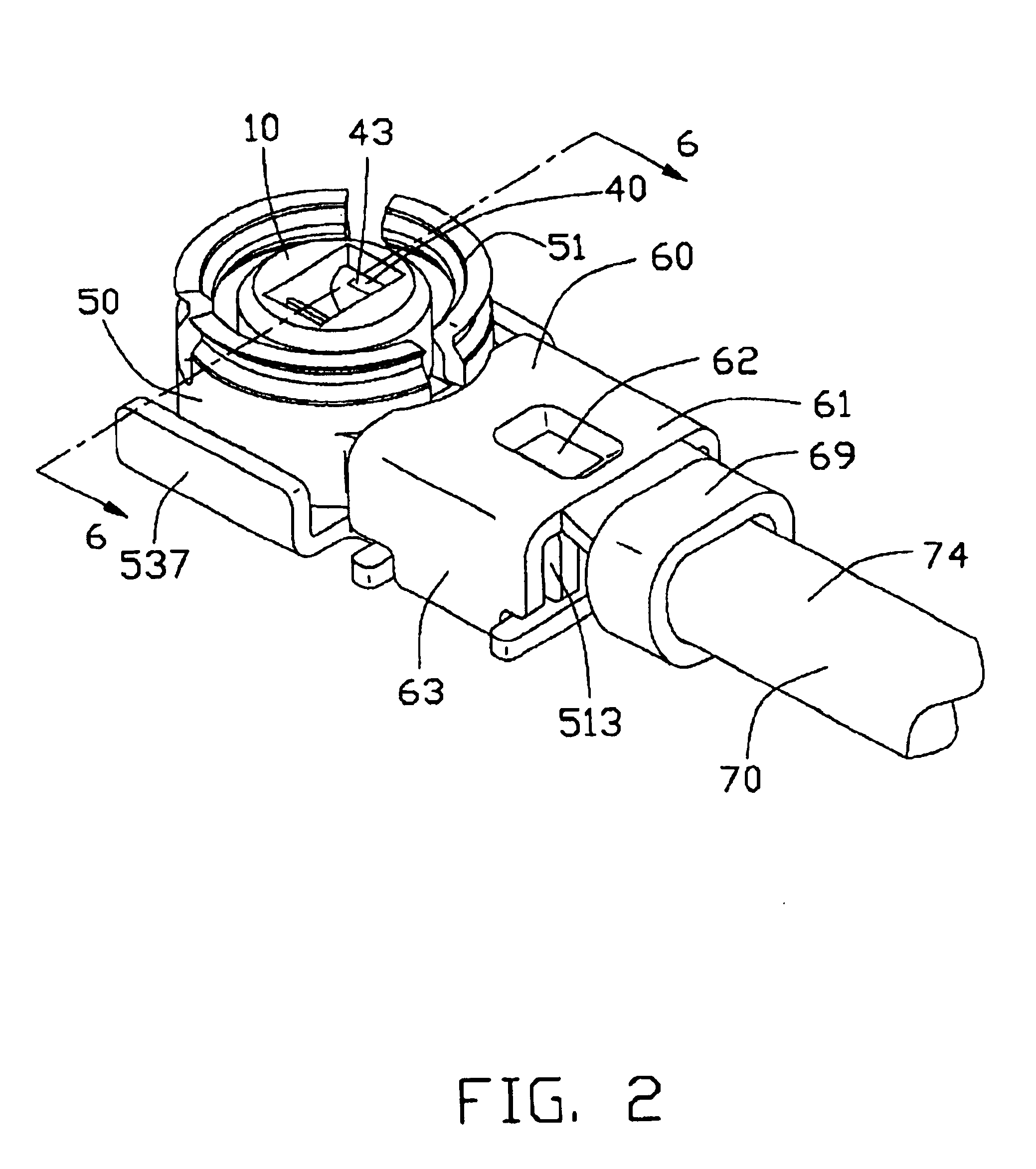
Referring to the drawings and particularly to FIGS. 1 and 2, a cable end connector in accordance with the present invention comprises a dielectric housing 10, a terminal 40, a metal shell 50 enclosing the housing 10 and the terminal 40, a circular thin layer insulator 1 and a retainer 60 for securing an end portion of a coaxial cable 70 to the cable end connector.

The dielectric housing 10 comprises a base portion 30 and a tubular portion 20. The base portion 30 comprises a front circular portion 31 and a rear rectangular portion 32 extending rearwardly from the circular portion 31. A pair of engaging blocks 33 protrude laterally from the circular portion 31 to abut against the shell 50. A rearwardly exposed groove 34 is defined in a bottom of the base portion 30. The tubular portion 20 axially and upwardly projects from the front circular portion 31. A substantially rectangular passageway 21 is axially defined through the front circular portion 31 and the tubular portion 20, and com...


PUM


Abstract

A cable end connector includes an insulative housing (10), a terminal (40) received in the housing, a metal shell (50) enclosing the housing, and an independent thin layer insulator (1). The independent thin layer insulator is located between the housing and the metal shell for insulating the terminal from the metal shell, whereby the cable end connector achieves a good insulation function between the terminal and the metal shell.

Description

BACKGROUND OF THE INVENTION1. Field of the InventionThe present invention relates to a connector, and more particularly to a low profile cable end connector for high frequency application.2. Description of the Prior ArtCable end connectors are often used for transmitting Radio-frequency (RF) signals. The cable end connector normally has a terminal received in a housing thereof to mate with a complementary connector, such as a header. Such a conventional cable end connector is, for example, disclosed in U.S. Pat. No. 5,322,453. The cable end connector includes a dielectric member holding a central terminal within an outer conductive shell. The dielectric member is substantially cylindrical and defines a coaxial passageway therein for receiving the terminal. A pair of small tabs projects from the terminal and abuts against an inner surface of the dielectric member, thereby retaining the terminal in the dielectric member. The outer conductive shell is bent at right angle to cover an op...

Claims


Application Information

Patent Timeline
IPC IPC(8): H01R9/05
CPCH01R9/0518
Inventor KO, DAVID TSO-CHIN
Owner HON HAI PRECISION IND CO LTD
Why Eureka
Try Eureka