Electric jack

a technology of electric jacks and jacks, applied in the direction of coupling contact members, coupling device connections, coupling/insulating coupling contact members, etc., to achieve the effect of improving productivity and avoiding excess mechanical stress

Inactive Publication Date: 2005-01-04
JST MFG CO LTD
View PDF17 Cites 38 Cited by
  • Summary
  • Abstract
  • Description
  • Claims
  • Application Information

AI Technical Summary

Benefits of technology

In analyzing a conventional jack structure, it is understood that the soldering portion under a mechanical stress may cause the crack. Then, according to the present invention, a jack contact and a lead are connected by crimping the lead at a crimping portion of the jack contact, and the crimping portion is disposed inside a housing of the jack so that it may avoid excess mechanical stress applied via the lead or directly by an operator.
Further, in order to improve the productivity, an opening for inserting the contact is disposed on a back side of the jack so that the contact may be easily put into the housing. The opening and an engaging and / or stopping structure such as lance, etc. for fixing the contact inside the housing so that the contact may perform its function may be closed or covered with the cover such that readjustment of the components inside the housing is not necessarily needed.

Problems solved by technology

In analyzing a conventional jack structure, it is understood that the soldering portion under a mechanical stress may cause the crack.

Method used


Image

  • Electric jack
  • Electric jack
  • Electric jack

Examples


Embodiment Construction

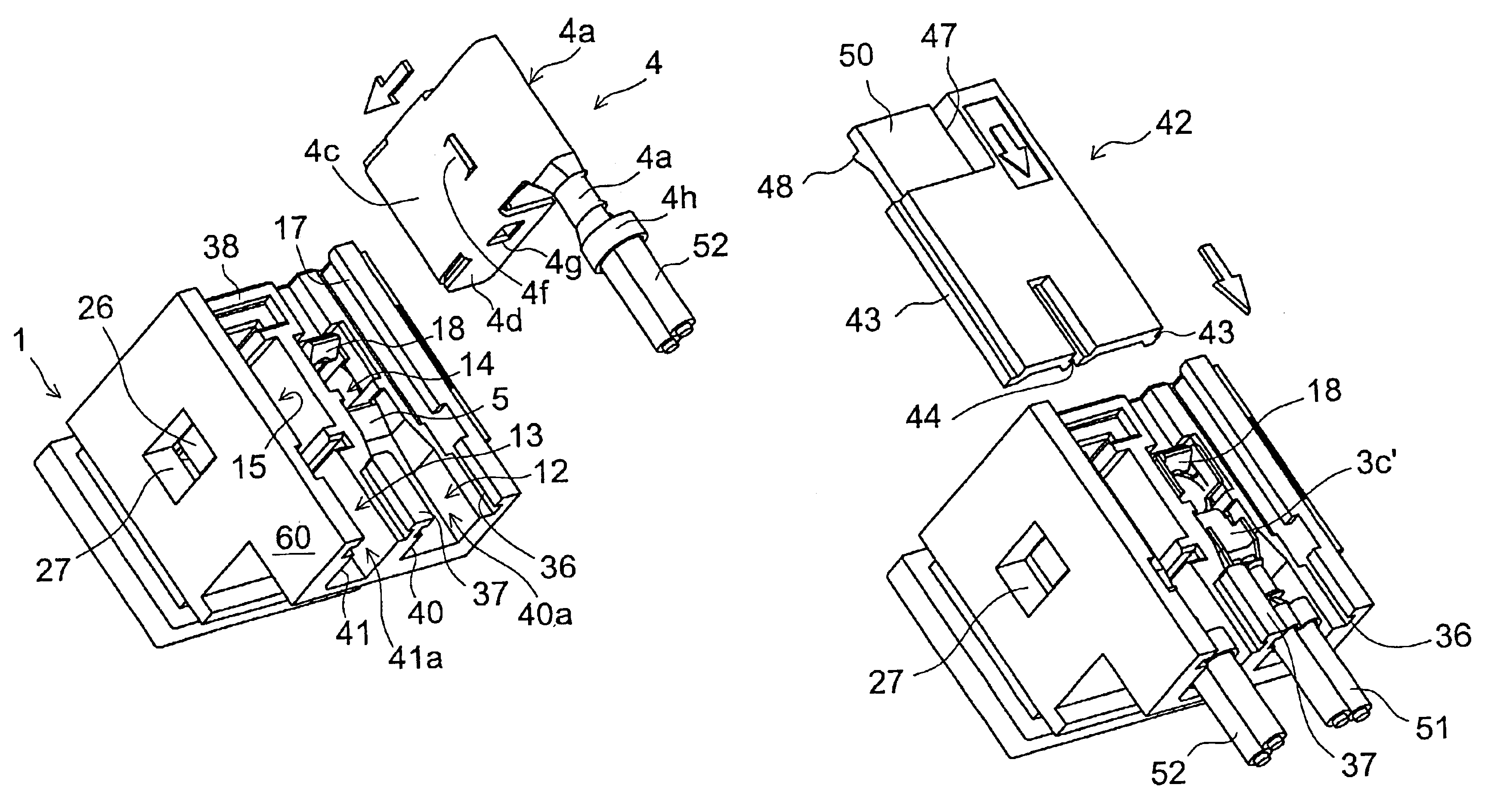
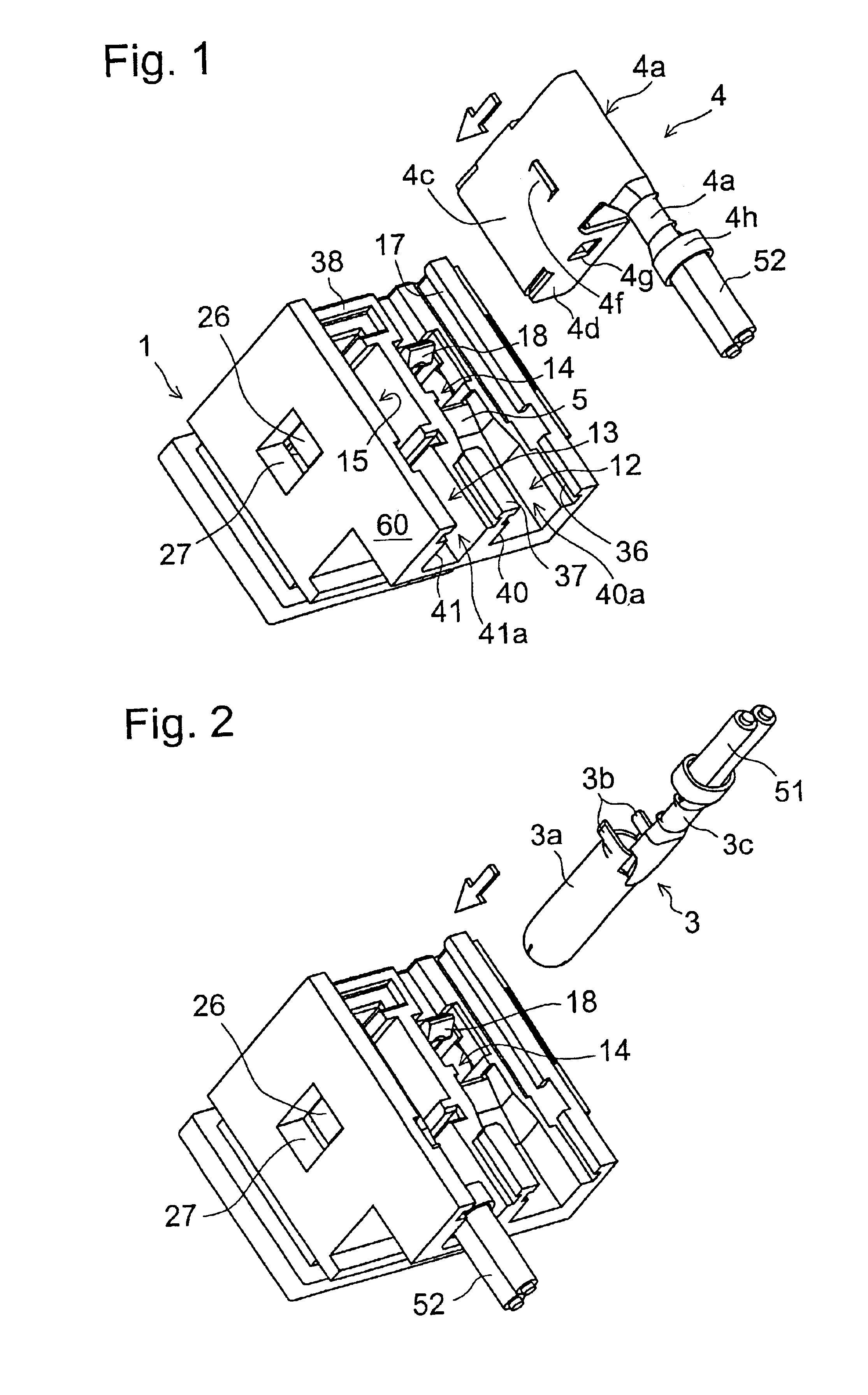
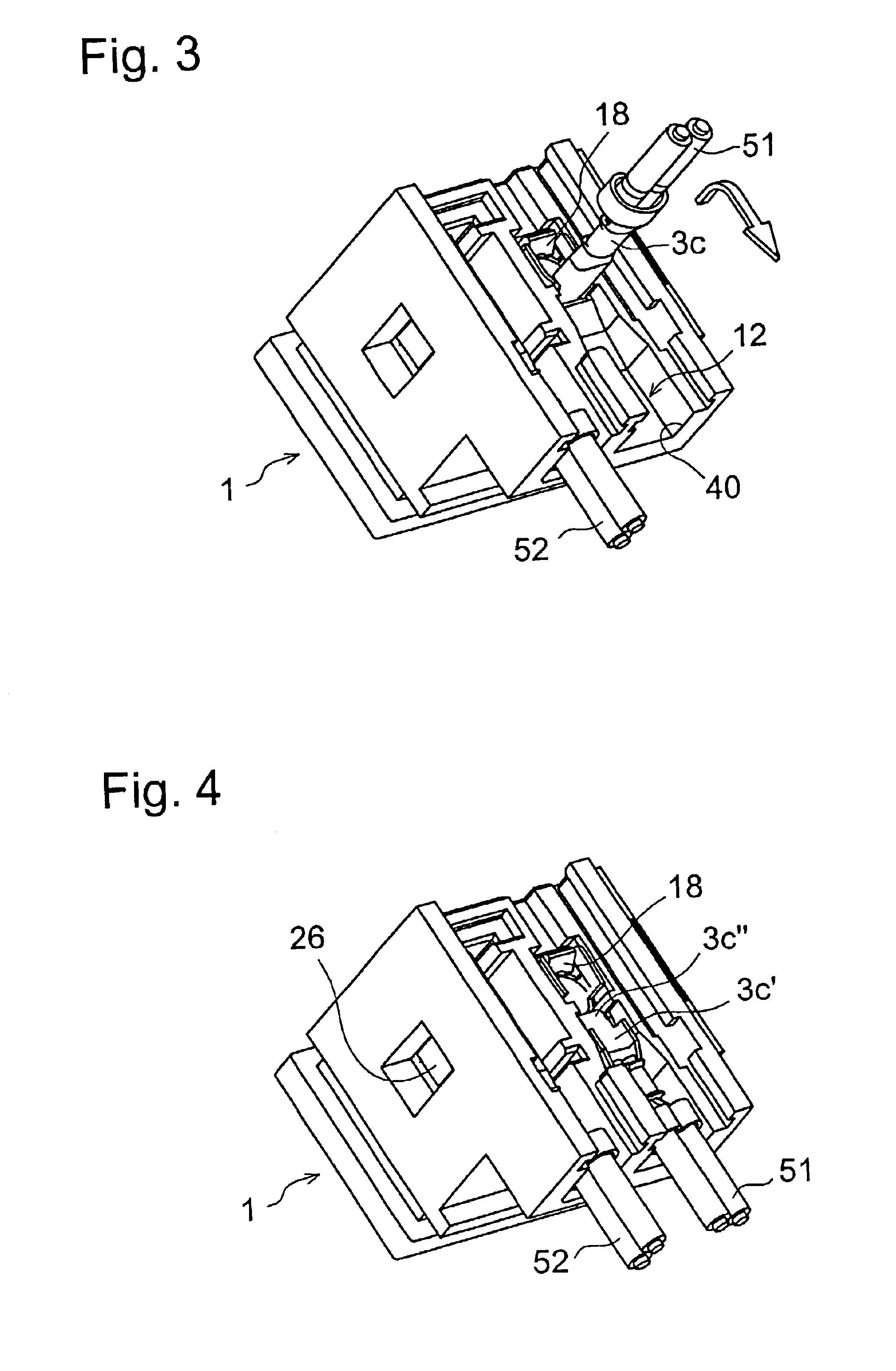
Hereafter, embodiments according to the present invention will be described in detail referring to the drawings, but the present invention is not limited to the embodiments. The embodiments are examples showing concrete shapes and materials according to the present invention.

First of all, the structural function of the present embodiment will be described briefly, and afterwards, in detail with reference to each figure. The inside of housing 1 has a contact insertion opening 7 arranged on the upper side of a partition 5 as shown in FIG. 13. Housing 1 is partitioned by a partition 8 into two kinds of contact insertion room 9 and 10. Crimping storage parts 12 and 13 are partitioned by a partition 11 into two (Refer to FIG. 9). A first opening 14 and a second opening 15 of the contact insertion hole are formed in a partition 5, and they are made to lead to the first insertion room 9 and the second insertion room 10, respectively (Refer to FIG. 13). The first insertion room 9 and the se...


PUM


Abstract

A jack, which would cause hardly a defective connection even if a mechanical deformation is received when attaching or using it, will be offered. The electric junction of contacts (3), (4) and leads (51), (52) is done by crimping, the crimping portions (3c), (4b) are arranged in a housing (1) of the jack which is not exposed easily to a mechanical deformation, and, in addition, the structure is so made that the mechanical force doesn't work easily on the crimping portions (3c), (4b) also by the leads (51), (52) extending from the jack.

Description

CROSS-REFERENCE TO RELATED APPLICATIONSThis application is based upon and claims the benefit of priority from the prior Japanese Patent Application No. 2002-131631, filed May 7, 2002, the entire contents of which are incorporated herein by reference. This application is related to co-pending United States patent application entitled “Connector Structure” filed on even date herewith. That co-pending application is also expressly incorporated herein by reference.BACKGROUND OF THE INVENTION1. Field of the InventionThe present invention relates to a jack which transmits the electric signal or energy and is used for a portable electronic device such as notebook computers and, more particularly, it relates to a structure of a housing, a contact, etc. being used for the jack.2. Background ArtMany portable electronic devices are operated with the direct current, and the voltage of domestic alternating current power is stepped down by an AC adaptor and at the same time converted into the dir...

Claims


Application Information

Patent Timeline
Patent Type & Authority Patents(United States)
IPC IPC(8): H01R13/00H01R13/56H01R13/428H01R13/432H01R13/502H01R13/506
CPCH01R13/562H01R13/432Y10S439/902H01R13/506H01R13/42H01R24/62
Inventor TAKADA, SYOICHIKIHIRA, SATORUWASHINO, KIYOSHIFUKAMI, TSUYOSHIKATO, MASATO
Owner JST MFG CO LTD
Why Eureka
Try Eureka