Specimen observation system for applying external magnetic field

a magnetic field and specimen technology, applied in the direction of magnetic discharge control, instruments, nuclear engineering, etc., can solve the problem of inability to observe or process specimens in a state in which a magnetic field of arbitrary magnitude in an arbitrary direction is applied

Inactive Publication Date: 2005-01-04
HITACHI LTD +1
View PDF2 Cites 14 Cited by
  • Summary
  • Abstract
  • Description
  • Claims
  • Application Information

AI Technical Summary

Benefits of technology

A charged particle beam 910 radiated from a condenser optical system (not shown) along an optical axis 900 reaches a point S0, however, the charged particle beam is rotated and is deflected by Lorentz force received from a magnetic field also distributed in front of the specimen (between the point S0 and the point S1) located at the point S1. That is, a charged particle is rotated with the optical axis as a tangential line and bends in a direction in which the beam is apart from the optical axis. Therefore, both a position and an angle in/at which the charged particle beam is radiated are different at the point S1 on the plane including the specimen, compared with those in case there is no magnetic field. The displacement is not a problem in an experiment in which a weak magnetic field is applied or in case an

Problems solved by technology

However, in this case, observation in a state in which a magnetic field of arbitrary magnitude in an arbitrary direction is applied to the specimen to be observed or to be processed

Method used


Image

  • Specimen observation system for applying external magnetic field
  • Specimen observation system for applying external magnetic field
  • Specimen observation system for applying external magnetic field

Examples


Embodiment Construction

FIG. 3 shows the basic configuration of a beam deflection system according to the invention. In this configuration, a specimen position corresponding to the point S4 described above is shown by a point S5. To simplify the description, only a transverse magnetic field is set as a magnetic field that acts upon a charged particle beam.

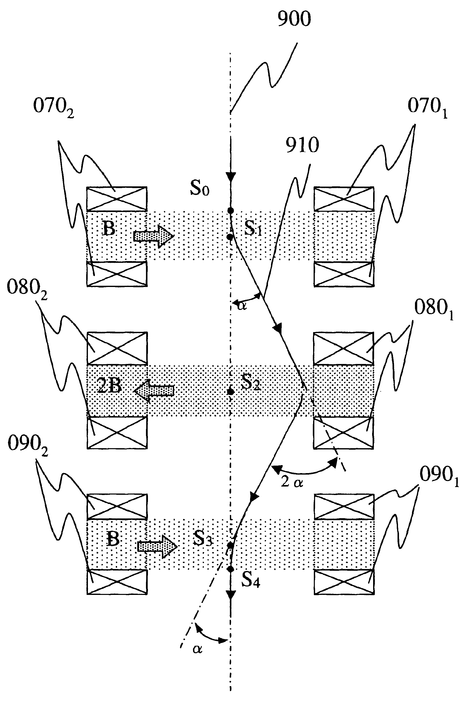
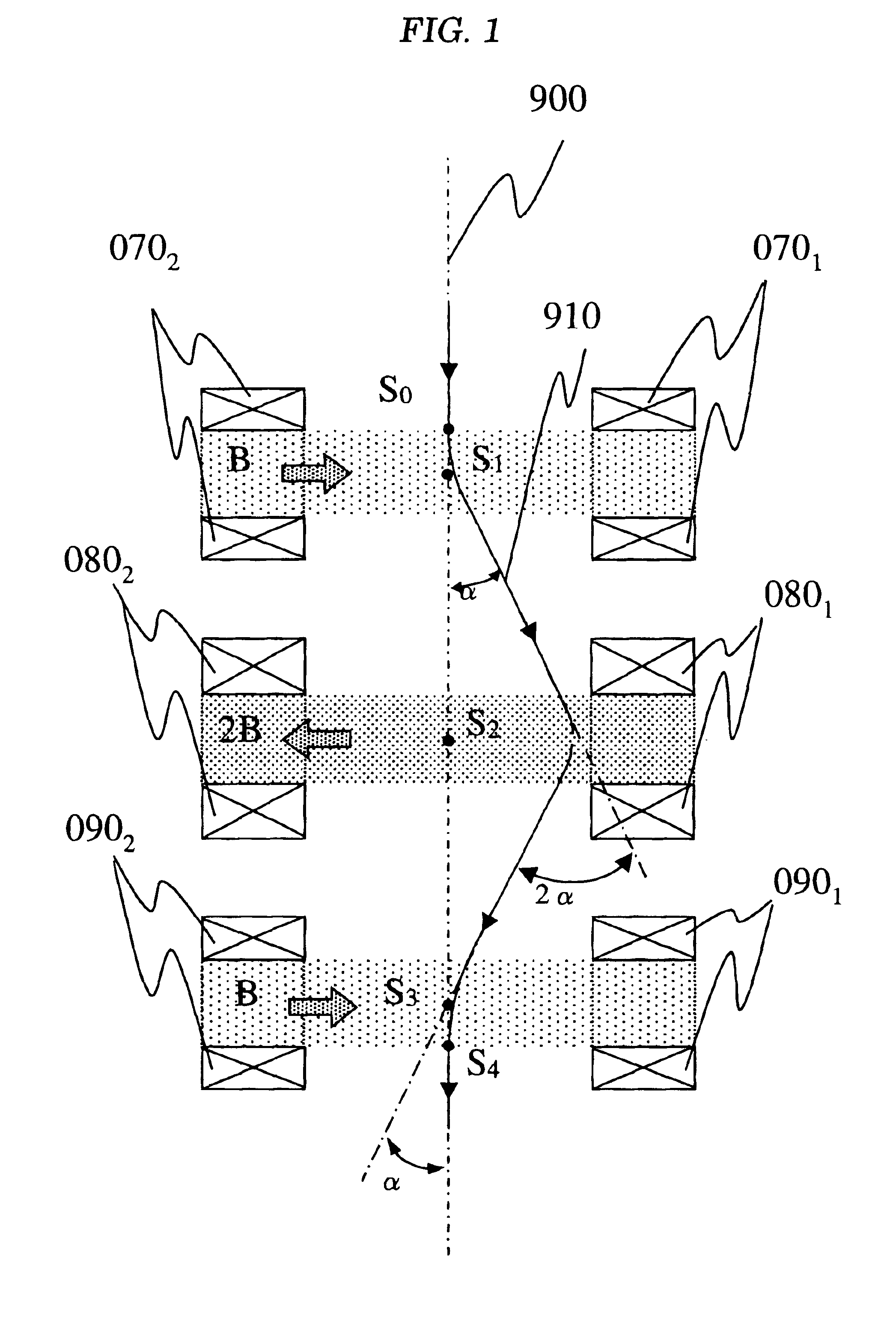
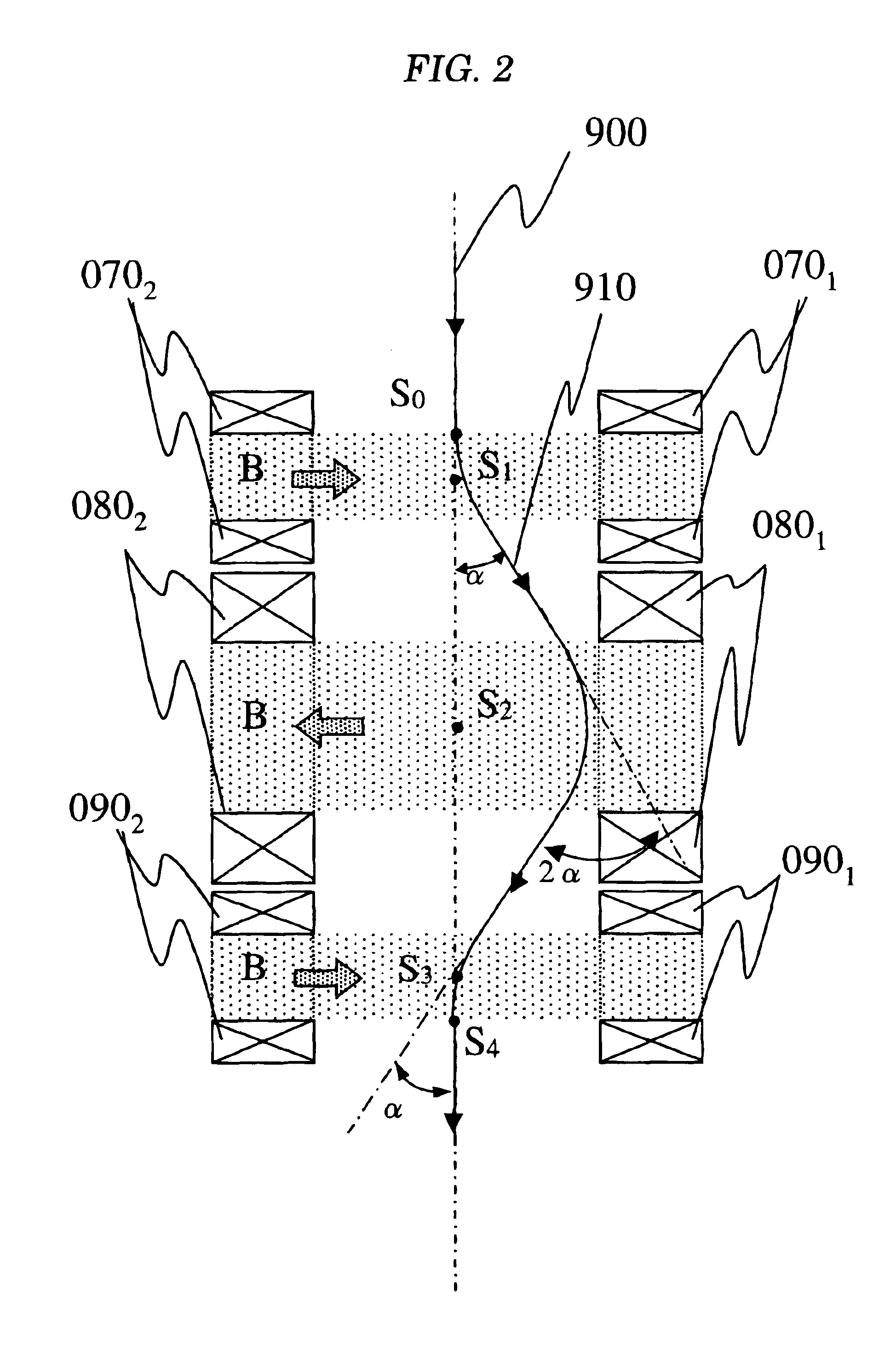
As shown in FIG. 3, reference numbers 900 and 910 denote an optical axis and a trajectory of a charged particle beam. Reference numbers 0101 and 0102 denote a pair of magnetic field applying coils and they generate a magnetic field B (a transverse magnetic field) in a direction shown by an arrow in FIG. 3. Reference numbers 0201 and 0202 similarly denote a pair of magnetic field applying coils and they also generate a magnetic field 2B (a transverse magnetic field) in a direction shown by an arrow in FIG. 3. It is similar to the description in relation to FIG. 1 that the trajectory of the charged particle beam 910 is deflected by an angle α by these two p...


PUM


Abstract

To prevent the displacement from an optical axis of a charged particle beam from being made independent of the direction (parallel to or perpendicular to the optical axis) of a magnetic field applied to a specimen, a system including an electron microscope and using a charged particle beam optical system is provided with a source of a charged particle beam, a condenser optical system, a specimen to be observed, a system for applying a magnetic field to the specimen, an imaging optical system and an image observation/recording apparatus, is provided with first and second charged particle beam deflection systems in order along a direction in which the charged particle beam travels between the condenser optical system and the specimen, is provided with third and fourth charged particle beam deflection systems in order between the specimen and the imaging lens system, and the quantity and the direction of the deflection of the charged particle beam by each deflection system and the intensity and the bearing of a magnetic field applied to the specimen are related according to predetermined relation.

Description

FIELD OF THE INVENTIONThe present invention relates to a specimen observation system for applying an external magnetic field having a magnetic field applying element suitable in case a magnetic field of arbitrary magnitude in an arbitrary direction is applied to a specimen to be observed or to be processed in an electron microscope or in a system having an optical system using a charged particle beam.BACKGROUND OF THE INVENTIONA magnetic lens is often used for a charged particle beam optical system to converge a charged particle beam and at that time, the optical axis of a charged particle beam is arranged so that it is coincident with the principal axis of the magnetic lens. Besides, to enhance the resolution of observation and the precision of processing, the diameter of a charged particle beam is required to be reduced. Therefore, a specimen is often arranged in the vicinity of a center position of a magnetic field generated by the magnetic lens. Above all, in a transmission elec...

Claims


Application Information

Patent Timeline
IPC IPC(8): H01J37/26H01J37/147G01N27/83G01N23/04G01Q20/02G01Q30/20G01R33/12H01J37/20
CPCH01J37/26H01J37/147
Inventor HARADA, KENENDO, JUNJIOSAKABE, NOBUYUKI
Owner HITACHI LTD
Why Eureka
Try Eureka