
Voltage converter utilizing independently switched inductors

Inactive Publication Date: 2005-01-04
INTEL CORP
View PDF6 Cites 35 Cited by
  • Summary
  • Abstract
  • Description
  • Claims
  • Application Information

AI Technical Summary

Problems solved by technology

Although electronics may not be readily visible, they can be very complicated.

Method used


Image

  • Voltage converter utilizing independently switched inductors
  • Voltage converter utilizing independently switched inductors
  • Voltage converter utilizing independently switched inductors

Examples


Embodiment Construction

Electrical hardware (e.g. a computer) may include many electrical devices. In fact, a computer may include millions of electrical devices (e.g. transistors, resistors, and capacitors). These electrical devices must work together in order for hardware to operate correctly. Accordingly, electrical devices of hardware may be electrically coupled together. This coupling may be either direct coupling (e.g. direct electrical connection) or indirect coupling (e.g. electrical communication through a series of components).

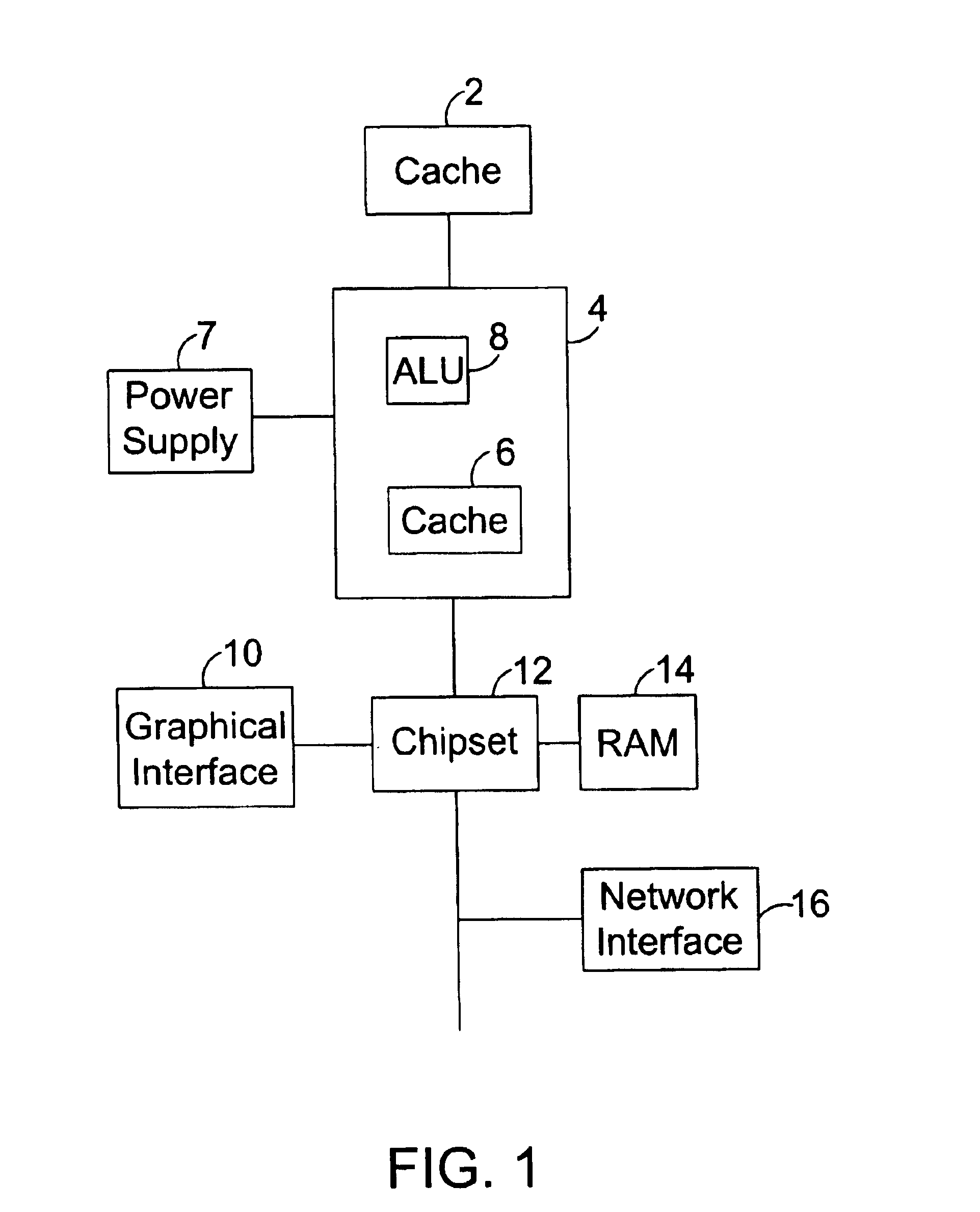
FIG. 1 is an exemplary global illustration of a computer. The computer may include a processor 4, which acts as a brain of the computer. Processor 4 may be formed on a die. Processor 4 may include an Arithmetic Logic Unit (ALU) 8 and may be included on the same die as processor 4. ALU 8 may be able to perform continuous calculations in order for the processor 4 to operate. Processor 4 may include cache memory 6 which may be for temporarily storing information. Cache memory ...


PUM


Abstract

Embodiments of the present invention relate to independently switched inductors in a voltage converter. Each voltage transforming inductor of a voltage converter may be deignated a switch or bridge at each opposing terminal. The function of these switches is to periodically reverse the polarity of voltage across the inductors. By configuring independently switched inductors in series, the frustration of voltage tolerance limitations of the switches is mitigated.

Description

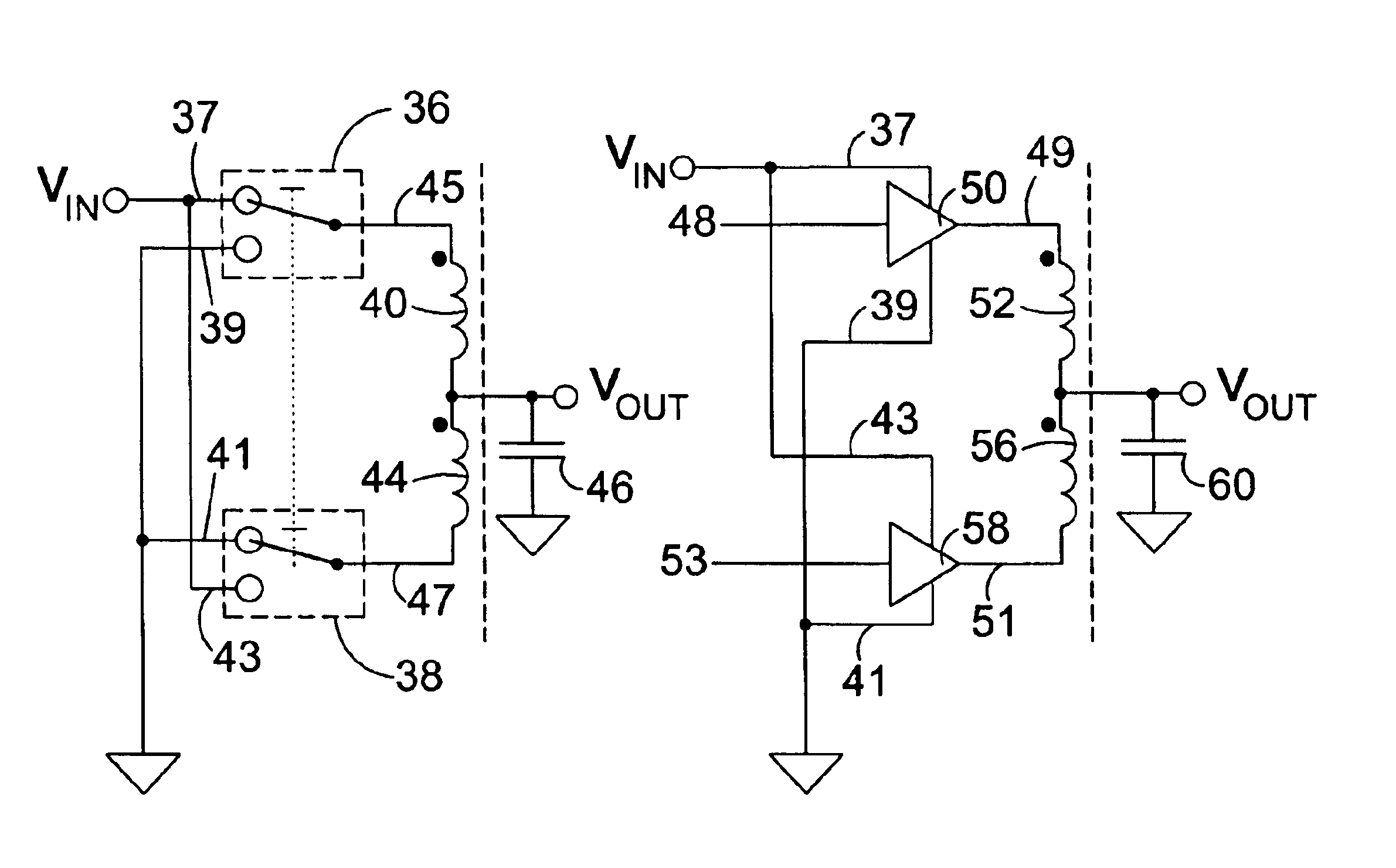
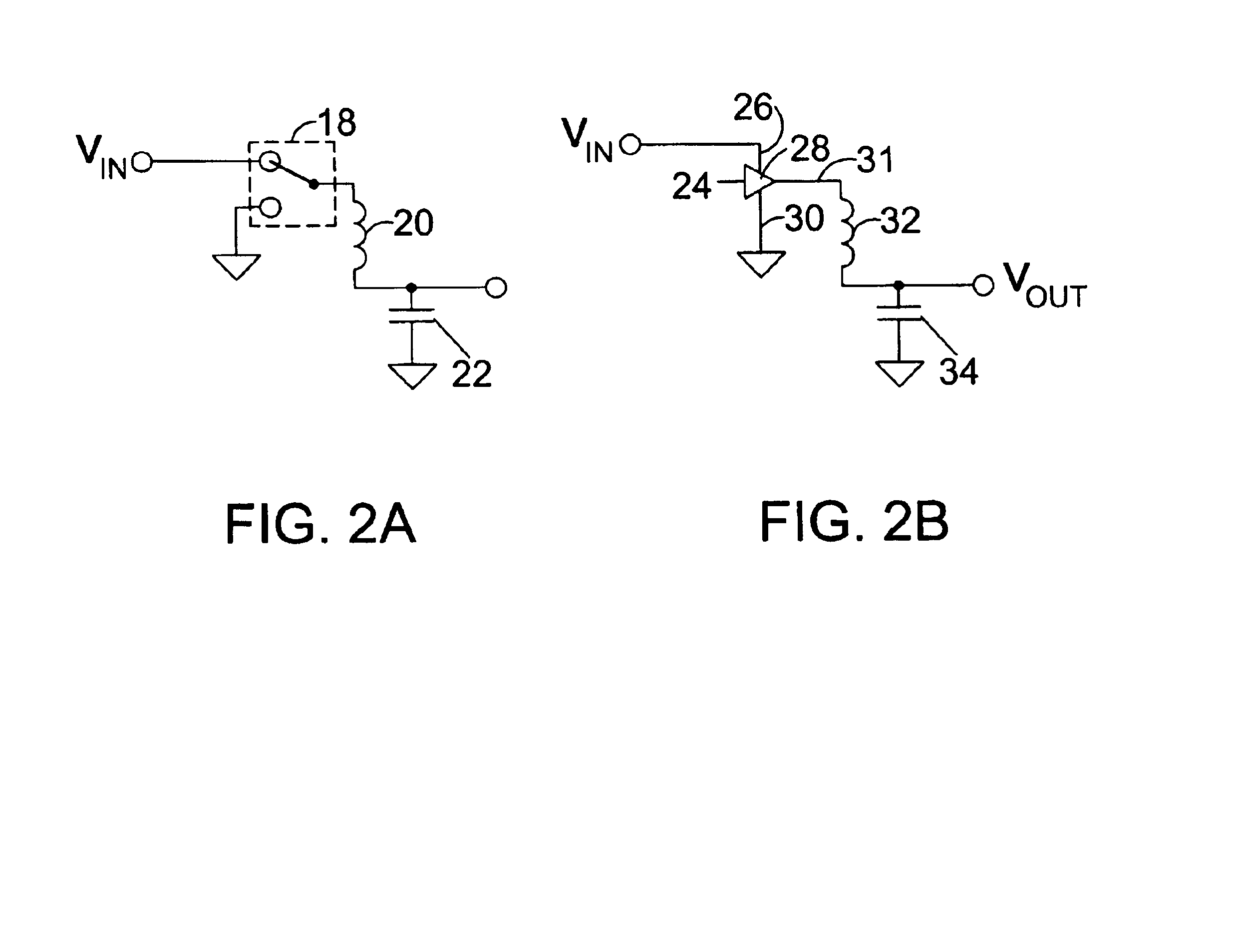
BACKGROUND OF THE INVENTION1. Field of the InventionThe field of the invention generally relates to electronics.2. Background of the Related ArtElectronics are very important in the lives of many people. In fact, electronics are present in almost all electrical devices (e.g. radios, televisions, toasters, and computers). Many times electronics are virtually invisible to the user because they can be made up of very small devices inside a case. Although electronics may not be readily visible, they can be very complicated. It may be desirable in many electrical devices for the electronics to become smaller and smaller. This may be desirable, as smaller devices are more portable and convenient to use by a user. Additionally, smaller electronic devices may actually work better as they are miniaturized (e.g., work faster or more efficiently).BRIEF DESCRIPTION OF THE DRAWINGSFIG. 1 is an exemplary global diagram of a portion of a computer.FIGS. 2A, 2B, 3A, 3B, 4A, and 4B are exemplary diag...

Claims


Application Information

Patent Timeline
IPC IPC(8): H01F29/02H01F29/00H02M3/158H02M3/337
CPCH01F29/02H02M3/1584H02M3/337H02M2001/009H02M2001/0074H02M2001/0077H02M1/0074H02M1/0077H02M1/009H02M3/33573
Inventor HAZUCHA, PETERSCHROM, GERHARDKARNIK, TANAYKURSUN, VOLKANNARENDRA, SIVA
Owner INTEL CORP
Learn More