Protable radio terminal testing apparatus using single self-complementary antenna

a portable radio terminal and self-complementary technology, applied in the direction of receiver monitoring, transmission monitoring, non-resonant long antennas, etc., can solve the problems of inability to cope with all the various types of portable radio terminals, inability to realize the entire antenna coupler at the same time, and failure to diagnose the faulty portable radio terminal sent to the manufacturer, etc., to achieve the effect of simple structure and easy operation

Inactive Publication Date: 2005-01-04
ANRITSU CORP
View PDF9 Cites 196 Cited by
  • Summary
  • Abstract
  • Description
  • Claims
  • Application Information

AI Technical Summary

Benefits of technology

An object of the present invention is to provide a portable radio terminal testing apparatus which solves the above-described problems, and which, with a simple structure, applicable of a wide frequency bandwidth, including the current frequency bandwidth and the frequency bandwidth expected for the future, and whose operation is easy, and which can correspond to various types of portable radio terminals whose shapes and antenna positions vary, and which uses a single self-complementary antenna as a coupling antenna.

Problems solved by technology

Accordingly, the conventional method, in which a faulty portable radio terminal is sent to the manufacturer to be diagnosed, is no longer satisfactory.
Therefore, in such an antenna coupler, since design of the coupled portion is not easy, and high manufacturing accuracy is required, there is the problem that the entire antenna coupler cannot be realized inexpensively.
Therefore, there is the problem that it cannot cope with all the various types of portable radio terminals whose shapes or antenna positions vary.

Method used


Image

  • Protable radio terminal testing apparatus using single self-complementary antenna
  • Protable radio terminal testing apparatus using single self-complementary antenna
  • Protable radio terminal testing apparatus using single self-complementary antenna

Examples


first embodiment

(First Embodiment)

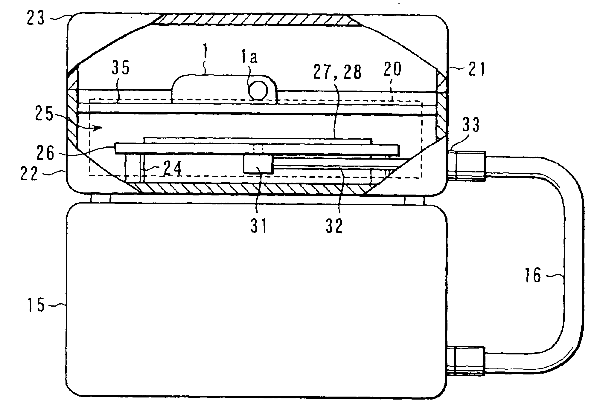
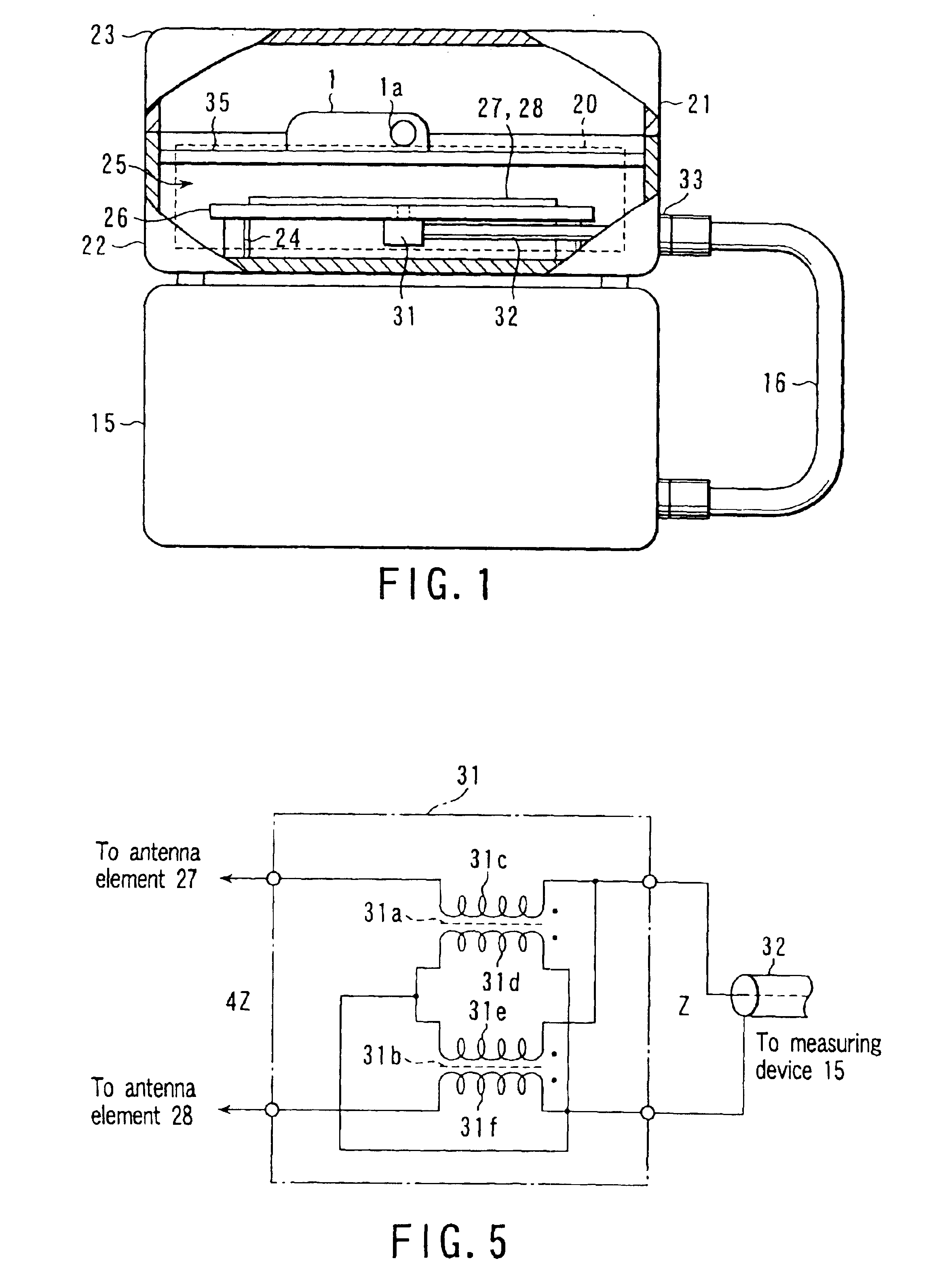
FIG. 1 is a sectional elevation showing an entire configuration in which a part of a shield box is cutaway when the shield box is used as a portable radio terminal testing apparatus according to a first embodiment of the present invention.

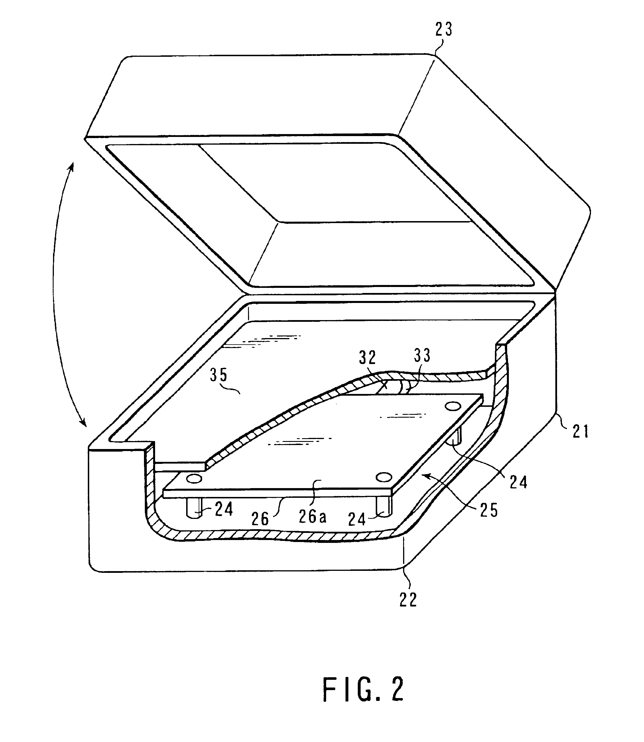
FIG. 2 is a perspective view showing a configuration of main portions in which a measuring device and connecting means are removed and a part of the shield box is cutaway when the shield box is used as the portable radio terminal testing apparatus according to the first embodiment of the present invention.

Further, in FIG. 2 illustrates, in particular, a portion of an antenna coupler 20 which is used in the portable radio terminal testing apparatus to which the present invention (hereinafter, simply called an antenna coupler) is applied and which is surrounded by the broken line frame in FIG. 1.

The antenna coupler 20 is provided in a shield box 21 for forming a space which is electromagnetically shielded from the exterior.

The shiel...

second embodiment

(Second Embodiment)

FIG. 12 is a perspective view showing a configuration of main portions in which the measuring device 15 and the connecting means 31 are removed and the shield box 21 is partially cutaway when the above-below arrangement of the coupling antenna 25 and the portable radio terminal 1 is reversed, as compared with FIG. 1, as a portable radio terminal testing apparatus according to a second embodiment of the present invention.

In the portable radio terminal testing apparatus according to the above-described first embodiment, the coupling antenna 25 is disposed at the bottom side of the lower case 22 of the shield box 21, and the placement member 35 is disposed thereabove.

On the contrary, as shown in FIG. 12, in the portable radio terminal testing apparatus according to the second embodiment, the coupling antenna 25 is attached along the inner wall of the upper case 23 of the shield box 21, and the portable radio terminal 1 is placed on the placement member 35 attached to...

third embodiment

(Third Embodiment)

FIG. 13 is a perspective view showing a configuration of main portions when a shield room 21A whose shielded space is large is used as a portable radio terminal testing apparatus according to a third embodiment of the present invention.

That is, as shown in FIG. 13, the portable radio terminal testing apparatus according to the third embodiment is formed from the shield room 21A, and the antenna coupler 20, the connecting means 32, and the measuring device 15 which are respectively accommodated within the shield room 21A.

In the portable radio terminal testing apparatus according to the above-described first and second embodiments, the space electromagnetically shielded from the exterior is formed from the shield box 21 whose size is suited for accommodating the portable radio terminal 1 and the antenna coupler 20.

On the other hand, in the portable radio terminal testing apparatus according to the third embodiment, the shielded space is the shield room 21A, which is ...


PUM


Abstract

A portable radio terminal testing apparatus has an antenna coupler 20, a connecting member 16, and a measuring device 15. The antenna coupler 20 has a placement member 35, a coupling antenna 25, a pair of through-connection portions, and an impedance transformer 31. The placement member 35 accepts a portable radio terminal 1, which is a testing object, in an unrestricted state. The coupling antenna 25 is disposed so as to be electromagnetically coupled with an antenna 19 of the portable radio terminal 1, and has a pair of antenna elements which are formed at one face side of a dielectric substrate 26 and which have a planar antenna structure of a predetermined shape, and a pair of feeding points, and is formed from a self-complementary antenna having a predetermined impedance within an operating frequency range including at least 800 MHz to 2.5 GHz order.

Description

TECHNICAL FIELDThe present invention relates to a portable radio terminal testing apparatus using a single self-complementary antenna and, more particularly to a portable radio terminal testing apparatus utilizing a technique applicable of a wide frequency bandwidth with a simple structure by using a self-complementary antenna as a coupling antenna when portable radio terminals, such as mobile cellular phones, or the like, are tested.BACKGROUND ARTIn recent years, due to the popularization of portable radio terminals, such as mobile cellular phones, portable information terminal machines, or the like, requests for trouble diagnosis and the like have greatly increased.Accordingly, the conventional method, in which a faulty portable radio terminal is sent to the manufacturer to be diagnosed, is no longer satisfactory.Therefore, in order to reduce the inconvenience to the user, a method involving fault diagnosis in shops, etc., is being used.In this way, in order for testing of portabl...

Claims


Application Information

Patent Timeline
Patent Type & Authority Patents(United States)
IPC IPC(8): H01Q1/38H01Q9/04H01Q1/24H01Q11/10H01Q9/28H01Q9/27H01Q11/00H04B7/005H04B17/00G01R29/08G01R31/28H04B17/17H04B17/29H04W88/02
CPCG01R29/0821H01Q1/241H01Q1/38H01Q9/27H01Q9/285H01Q11/10H01Q1/242G01R29/0871G01R29/0878H04W52/52
Inventor TESHIROGI, TASUKUOTONARI, NOBUTOSHI
Owner ANRITSU CORP
Why Eureka
Try Eureka