Light beam display with interlaced light beam scanning

a light beam and display screen technology, applied in the field of display and display methods, can solve the problems of limited scanning accuracy of light beams over display screens, display failures to be widely used, and inability to meet the above desirable characteristics, so as to achieve accurate scanning of the entire display area and minimize the amount of vertical shifting

Inactive Publication Date: 2005-01-04
PRYSM SYST INC
View PDF28 Cites 61 Cited by
  • Summary
  • Abstract
  • Description
  • Claims
  • Application Information

AI Technical Summary

Benefits of technology

In a first aspect, the present invention provides a light beam display comprising a display screen having a vertical and a horizontal dimension, a source of a plurality of light beams and an optical path including a movable reflector having a plurality of reflective facets between the display screen and the light beam source. The movable reflector directs the plural light beams to the display screen via one or more facets of the movable reflector to simultaneously illuminate plural different scan lines of the display which are spaced apart by plural non-illuminated scan lines. An optical mechanical element is provided for vertically shifting the light beams so as to illuminate different scan lines of the display screen. This interlacing of the horizontal scan lines allows the amount of vertical shifting to be minimized allowing very accurate scanning of the entire display area.

Problems solved by technology

Although a number of approaches have been employed including CRT displays, rear projection and front projection displays, plasma displays and LCDs, none of these have been able to satisfactorily provide all the above desirable characteristics.
Although light beam based displays such as light emitting diode or laser beam displays potentially can provide many advantages for displays of both types noted above, such displays have not been widely employed.
This is due in large part to limitations in the ability to scan the light beam over the display screen with the needed accuracy.
It will be appreciated by those skilled in the art that as the size of the display and the resolution of the display increase it becomes extremely difficult to maintain the needed precise alignment of the two moving mirrors.
Various types of distortion can result which are unacceptable for high resolution applications such as HDTV.
These factors present serious problems for providing a commercially acceptable scanned laser or light beam display.

Method used


Image

  • Light beam display with interlaced light beam scanning
  • Light beam display with interlaced light beam scanning
  • Light beam display with interlaced light beam scanning

Examples


Embodiment Construction

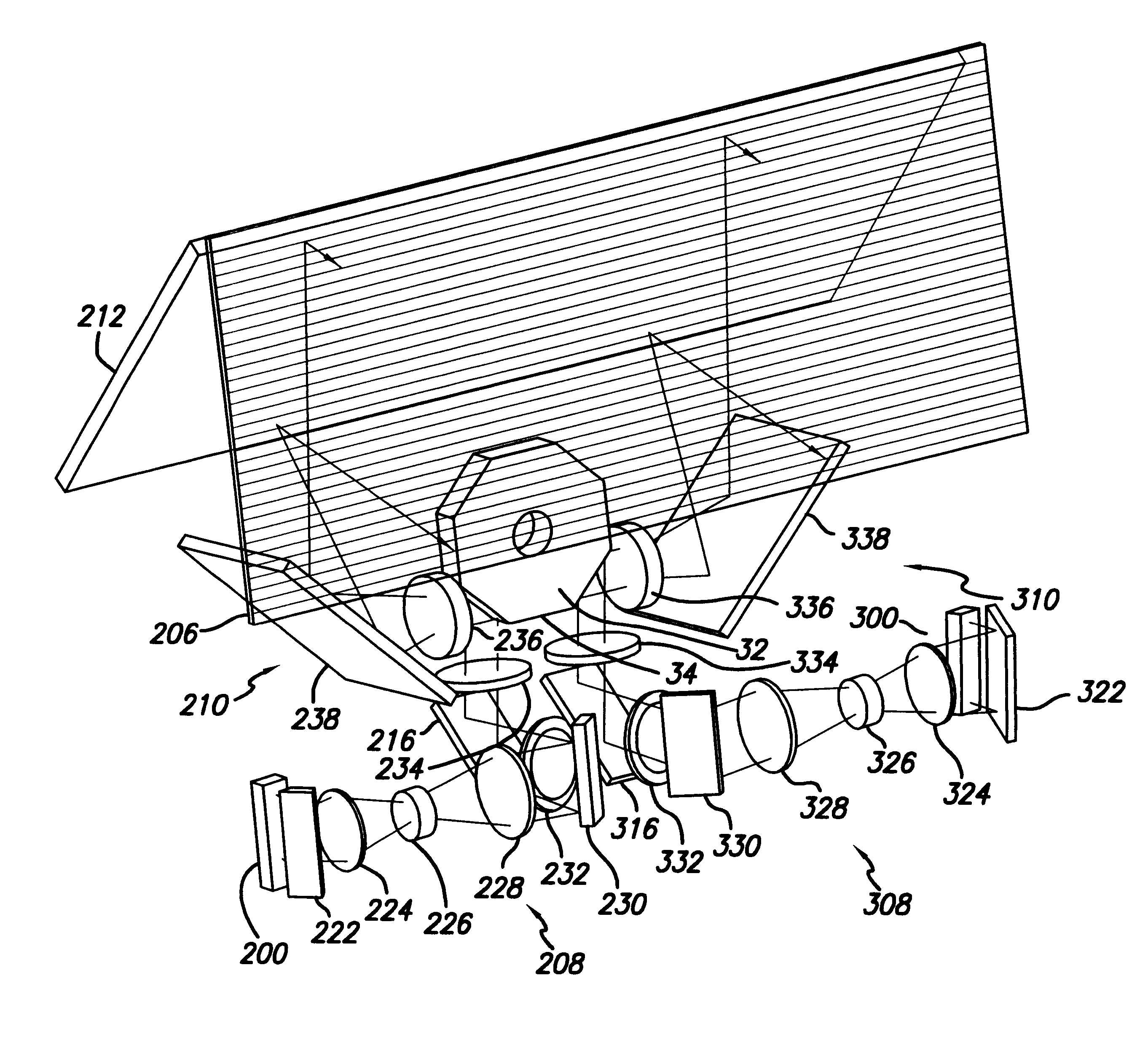
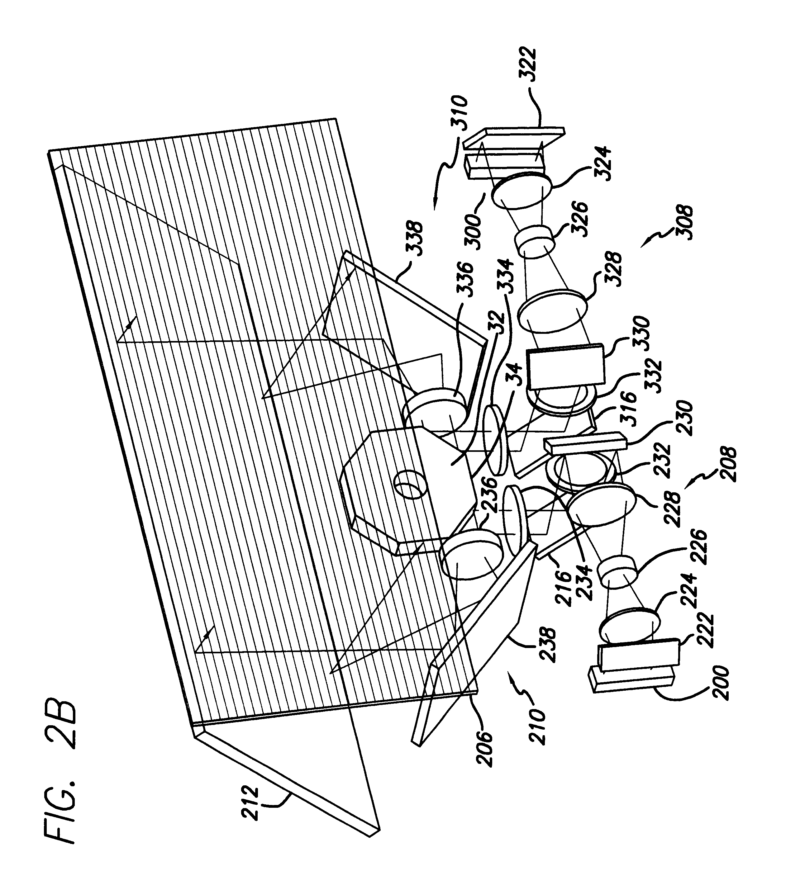
Referring to FIG. 2A and FIG. 2B, a preferred embodiment of the light beam display of the present invention is illustrated in a schematic drawing illustrating the basic structure and electronics of the embodiment. The dimensions of the structural components and optical path are not shown to scale in FIG. 2B, and the specific dimensions and layout of the optical path will depend upon the specific application. The light beam sources, multi-faceted polygon and other optics, and the display electronics may employ the teachings of the U.S. patent application Ser. No. 09 / 169,163 filed Oct. 8, 1998, now U.S. Pat. No. 6,175,440, issued Jan. 16, 2001, the disclosure of which is incorporated herein by reference. The teachings of U.S. Pat. No. 6,008,925 issued Dec. 28, 1999; U.S. Pat. No. 5,646,766 issued Jul. 8, 1997 and U.S. Pat. No. 5,166,944 issued Nov. 24, 1992; the disclosures of which are incorporated herein by reference, may also be employed. Accordingly, the following will not describ...


PUM


Abstract

A light beam display employing interlaced light beam scanning comprising a display screen having a vertical and a horizontal dimension, a source of a plurality of light beams and an optical path including a movable reflector having a plurality of reflective facets between the display screen and the light beam source. The movable reflector directs the plural light beams to the display screen via one or more facets of the movable reflector to simultaneously illuminate plural different scan lines of the display which are spaced apart by plural non-illuminated scan lines. An optical mechanical element is provided for vertically shifting the light beams so as to illuminate different scan lines of the display screen.

Description

BACKGROUND OF THE INVENTION1. Field of the InventionThe present invention relates to displays and methods of displaying video information. More particularly, the present invention relates to light beam displays and methods of scanning light beams to display video information.2. Description of the Prior Art and Related InformationHigh resolution displays have a variety of applications, including computer monitors, HDTV and simulators. In such applications, the primary considerations are resolution, maximum viewable area, cost and reliability. Although a number of approaches have been employed including CRT displays, rear projection and front projection displays, plasma displays and LCDs, none of these have been able to satisfactorily provide all the above desirable characteristics. In other display applications, such as control panel displays, and vehicle and aircraft on-board displays, resolution is of less importance than brightness, compact size and reliability.Although light beam...

Claims


Application Information

Patent Timeline
Patent Type & Authority Patents(United States)
IPC IPC(8): G09G3/02G02B26/10G02B26/12H04N3/08H04N5/66
CPCG09G3/02G09G2310/0227G02F1/13
Inventor CONEMAC, DONALD C.FORD, ERIC HARLEN
Owner PRYSM SYST INC
Why Eureka
Try Eureka