Method and apparatus for diagnosing damages of conductive materials

a technology of conductive materials and damage detection, applied in the direction of mechanical measurement arrangements, mechanical roughness/irregularity measurements, instruments, etc., can solve the problems of inability to evaluate a pile-up structure comprising a plurality of piled-up layers of conductive materials, and inability to diagnose or evaluate the second

Inactive Publication Date: 2005-01-04
EBARA CORP
View PDF13 Cites 8 Cited by
  • Summary
  • Abstract
  • Description
  • Claims
  • Application Information

AI Technical Summary

Benefits of technology

The conventional non-destructive method of diagnosing a conductive material using an electro-magnetic acoustic transducer is applicable to a case where an object to be diagnosed is a monolithic conductive material through which ultrasonic waves can pass, but incapable of evaluating a piled up structure comprising a plurality of piled up layers of conductive materials. That is, the conventional diagnosing method using an electro-magnetic acoustic transducer is capable of evaluating the uppermost layer of a piled up structure but incapable of diagnosing or evaluating the second layer, the third layer and so forth, which are disposed successively below the uppermost layer. A first object of the present invention is to provide a diagnosing method and apparatus capable of evaluating flaws, defects, grain boundaries, changes of material's structure, etc. in each of the second and following layers of a piled up structure from above the surface of the first layer of a conductive material in a non-contact manner by using an electro-magnetic acoustic transducer (EMAT).

Problems solved by technology

The conventional non-destructive method of diagnosing a conductive material using an electro-magnetic acoustic transducer is applicable to a case where an object to be diagnosed is a monolithic conductive material through which ultrasonic waves can pass, but incapable of evaluating a piled up structure comprising a plurality of piled up layers of conductive materials.
That is, the conventional diagnosing method using an electro-magnetic acoustic transducer is capable of evaluating the uppermost layer of a piled up structure but incapable of diagnosing or evaluating the second layer, the third layer and so forth, which are disposed successively below the uppermost layer.

Method used


Image

  • Method and apparatus for diagnosing damages of conductive materials
  • Method and apparatus for diagnosing damages of conductive materials
  • Method and apparatus for diagnosing damages of conductive materials

Examples


Embodiment Construction

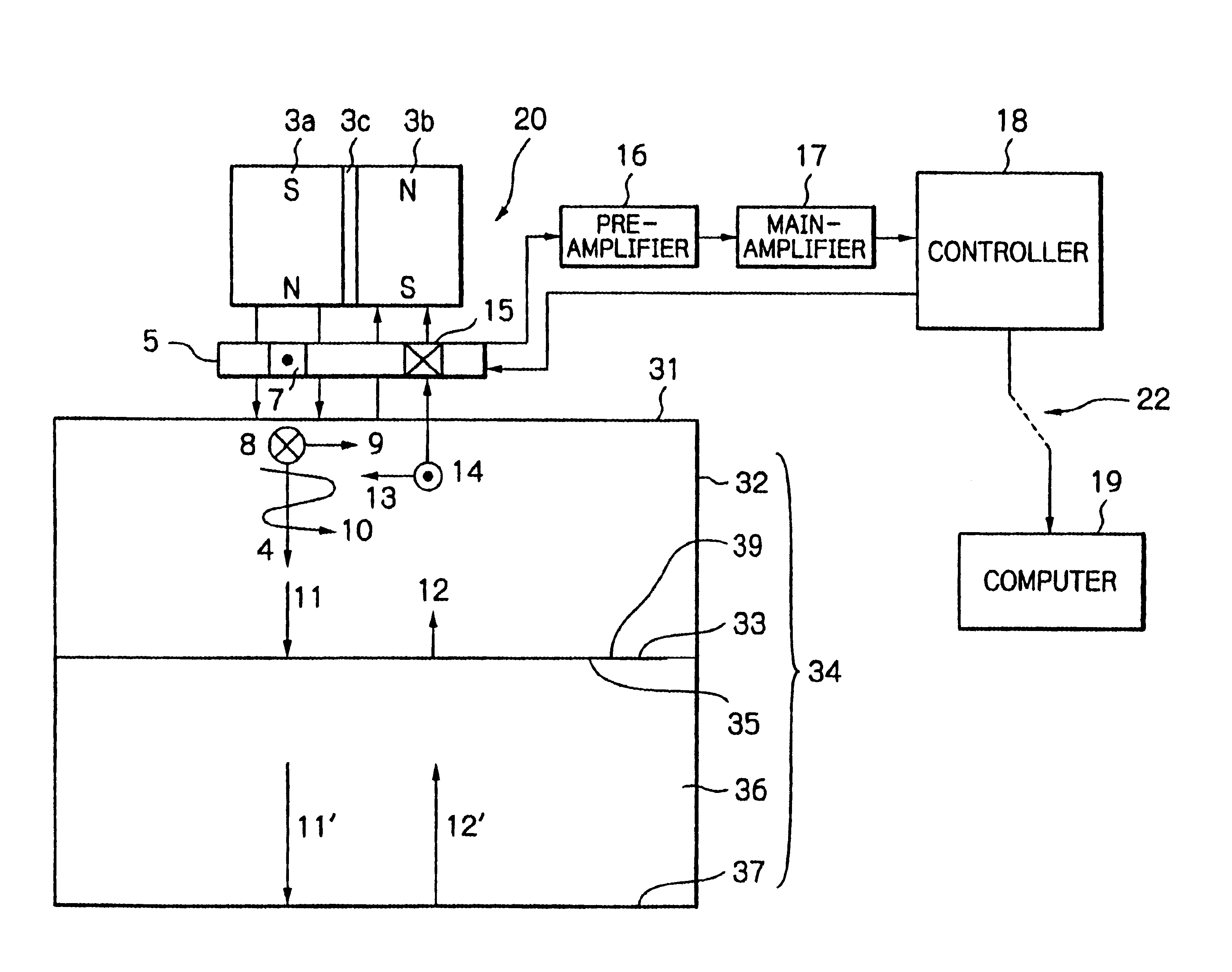
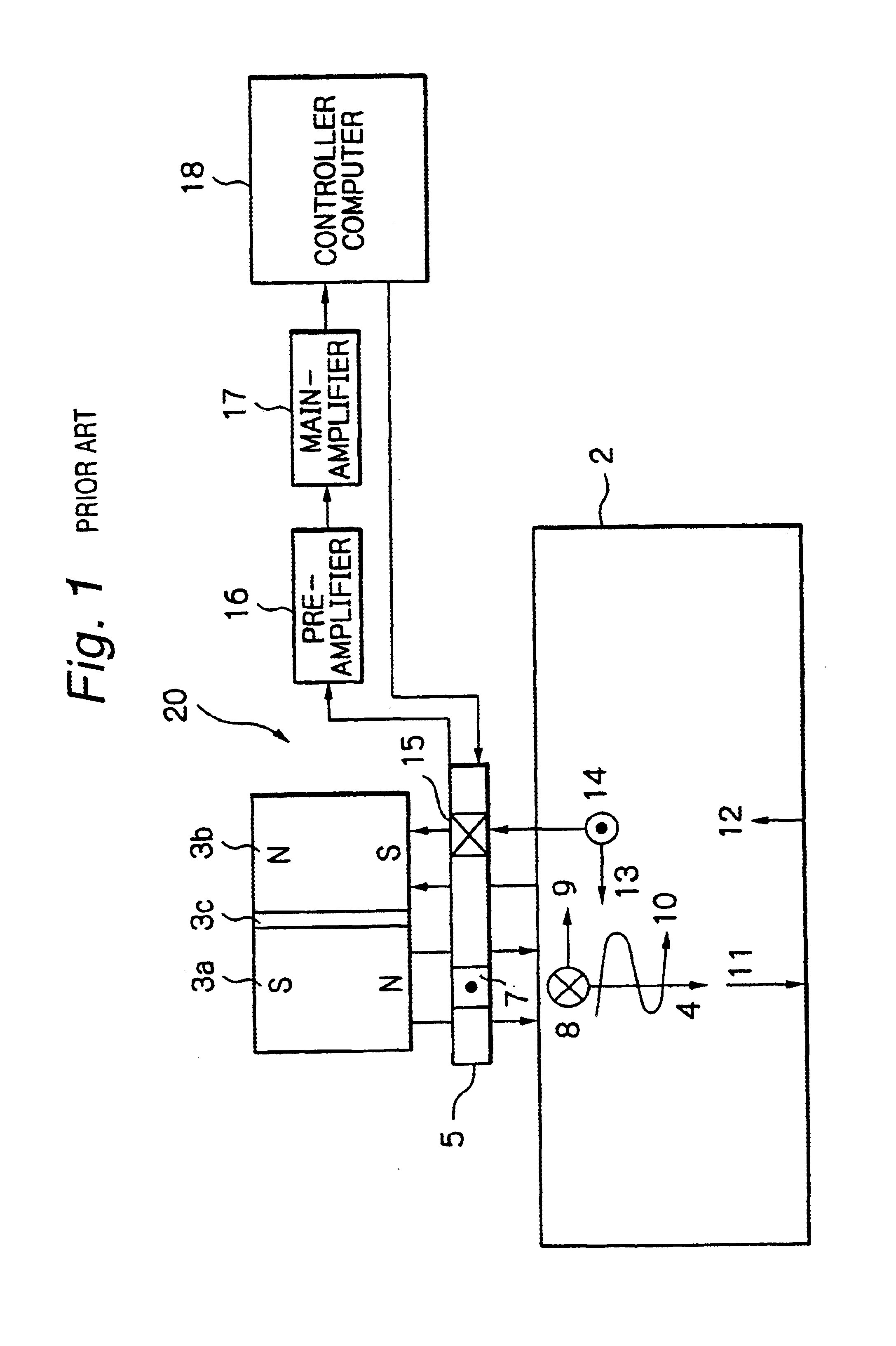
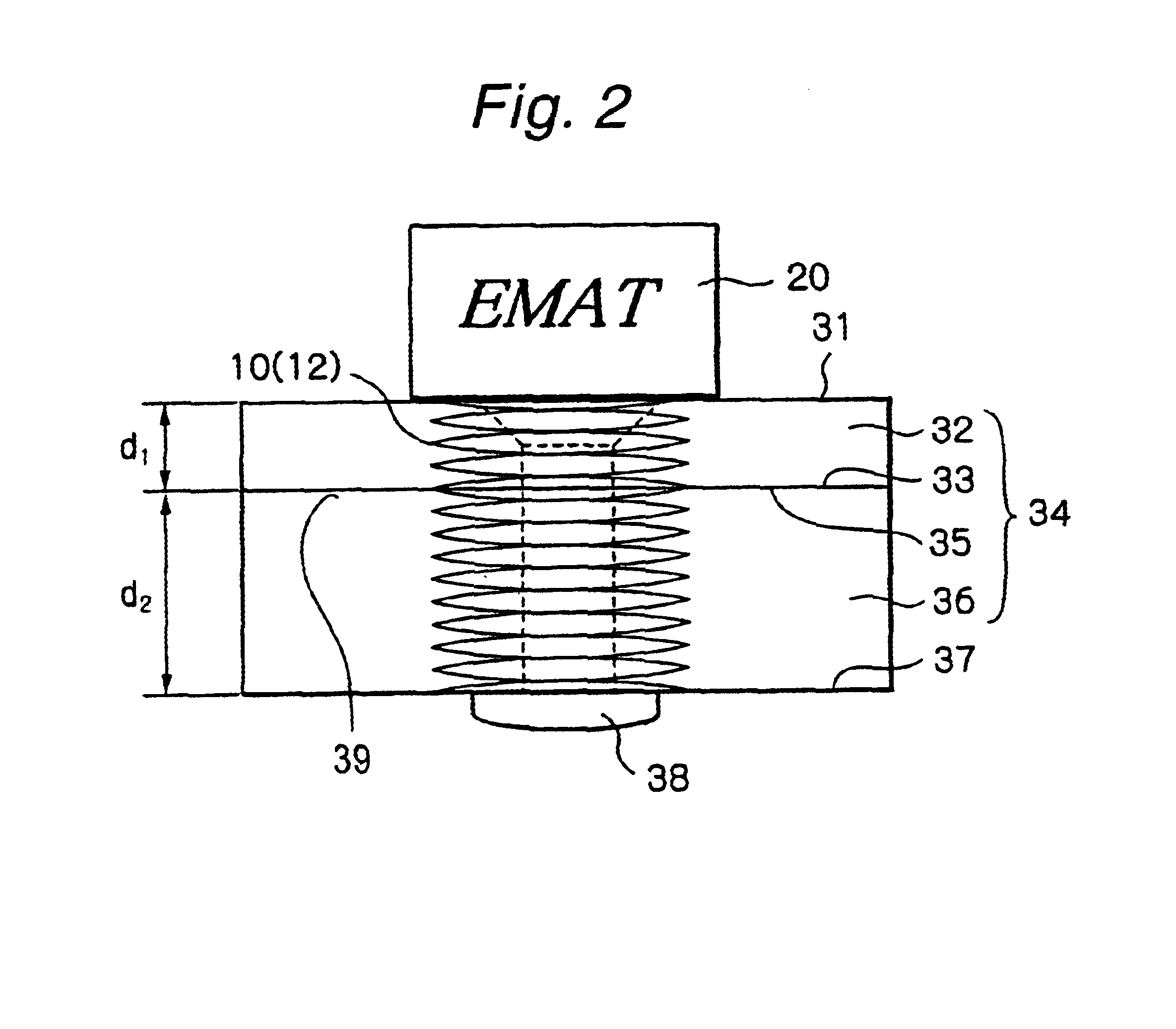
FIG. 2 is a diagram showing the principle of the present invention. In FIG. 2, an object to be diagnosed is a piled up structure 34 comprising a first layer 32 of a conductive material and a second layer 36 of a conductive material that are fastened together with a rivet 38. An electro-magnetic acoustic transducer EMAT 20 is disposed adjacent to the upper surface 31 of the piled up structure 34. The EMAT 20 has a pair of permanent magnets, together with a driver coil and a detection coil, in the same way as shown in FIG. 1. The EMAT 20 is positioned so that all ultrasonic waves generated by the EMAT 20 will not pass through the rivet 38. The uppermost surface 31 of the piled up structure 34 may be covered with a non-conductive material, e.g. paint, because the EMAT 20 can generate ultrasonic waves in the structure in a non-contact manner.

When a radio-frequency current is supplied to the driver coil of the EMAT 20, ultrasonic waves 10 are generated in the first layer 32 as in the cas...


PUM

PropertyMeasurementUnit
thicknessaaaaaaaaaa
thicknessaaaaaaaaaa
thicknessaaaaaaaaaa

Abstract

A diagnosing method and apparatus non-destructively performing damage evaluation of a piled up structure of conductive materials by using acoustic waves. The diagnosing method according to the present invention includes the steps of placing an electro-magnetic acoustic transducer 20 out of contact with a piled up structure 34 of conductive materials 32 and 34 piled up with a non-conductive interface 33 (35) interposed therebetween, transmitting ultrasonic waves from one side 31 of the piled up structure by the electro-magnetic acoustic transducer 20, receiving ultrasonic waves reflected from the other side of the piled up structure, and diagnosing a damaged condition of the piled up structure on the basis of the ultrasonic velocity and attenuation of the received ultrasonic waves.

Description

BACKGROUND OF THE INVENTIONThe present invention relates to a method and apparatus for diagnosing damage to electrically conductive materials, e.g. corrosion or fatigue, by using an ultrasonic resonance method. With the ultrasonic resonance method, ultrasonic waves are transmitted and received through a conductive material by an EMAT (Electro-Magnetic Acoustic Transducer) disposed adjacent to the surface of the conductive material. More specifically, the present invention relates to a method and apparatus for diagnosing by using an EMAT a damaged condition, e.g. corrosion, creep, stress-corrosion crack, or fatigue, of a piled up or laminated structure of conductive materials fastened together with rivets, bolts or the like.Electro-magnetic acoustic transducers (EMATs) have been disclosed, for example, in the Gazette of Japanese Patent No. 3052049 and the Gazette of Japanese Patent No. 3052050. FIG. 1 is a diagram for explaining the principle of a publicly known electro-magnetic acou...

Claims


Application Information

Patent Timeline
Patent Type & Authority Patents(United States)
IPC IPC(8): G01N29/11G01N29/24G01N29/07G01N29/04G01N29/12
CPCB21J15/285G01N29/07G01N29/11G01N29/2412G01N2291/011G01N2291/044G01N2291/0231G01N2291/0258G01N2291/02827G01N2291/0422G01N2291/015
Inventor OHTANI, TOSHIHIRO
Owner EBARA CORP
Why Eureka
Try Eureka