Portal trace detection systems for detection of imbedded particles

a technology of imbedded particles and detection systems, applied in the field of detection apparatuses, can solve problems such as adverse effects achieve the effects of reducing or eliminating the effect of jets on human thermal plumes, reducing or eliminating the effect of particles, and increasing the release of particles

Inactive Publication Date: 2005-01-11
RAPISCAN SYST INC (US)
View PDF12 Cites 40 Cited by
  • Summary
  • Abstract
  • Description
  • Claims
  • Application Information

AI Technical Summary

Benefits of technology

The jets may be connected to a high pressure (40-100 psi) air supply and may be operated sequentially by solenoid valves that are connected to and operated by a controller. Each jet is operative to deliver a short puff of air which disturbs the clothing of the human suspect sufficiently to release trapped particles. The air flow created by the jets necessarily disturbs the body plume somewhat, and hence conceivably could cause a turbulence that could direct particles of interest out of the portal. However, the effect of the jets on the human thermal plume can be minimized substantially by operating each jet only for a very short duration. Thus, each jet functions essentially like a smoke ring with a local disturbance, but a minimum effect on air flow patterns in the human thermal plume. Furthermore, the effect of the short puffs of air produced by the jet can be used cooperatively with the human thermal plume by actuating the jets sequentially from bottom to top in each of the vertical arrays of jets. The jets preferably are switched on for about 10-80 ms, and each level of jets is switched off before the next level is switched on. It has been determined that longer periods of operation for the respective jets adversely affects the human thermal plume without significantly increasing the release of particles from the clothing of the

Problems solved by technology

The air flow created by the jets necessarily disturbs the body plume somewhat, and hence conceivably could cause a turbulence that could direct particles of interest out of the portal.
It has been determined that lon

Method used


Image

  • Portal trace detection systems for detection of imbedded particles
  • Portal trace detection systems for detection of imbedded particles

Examples


Embodiment Construction

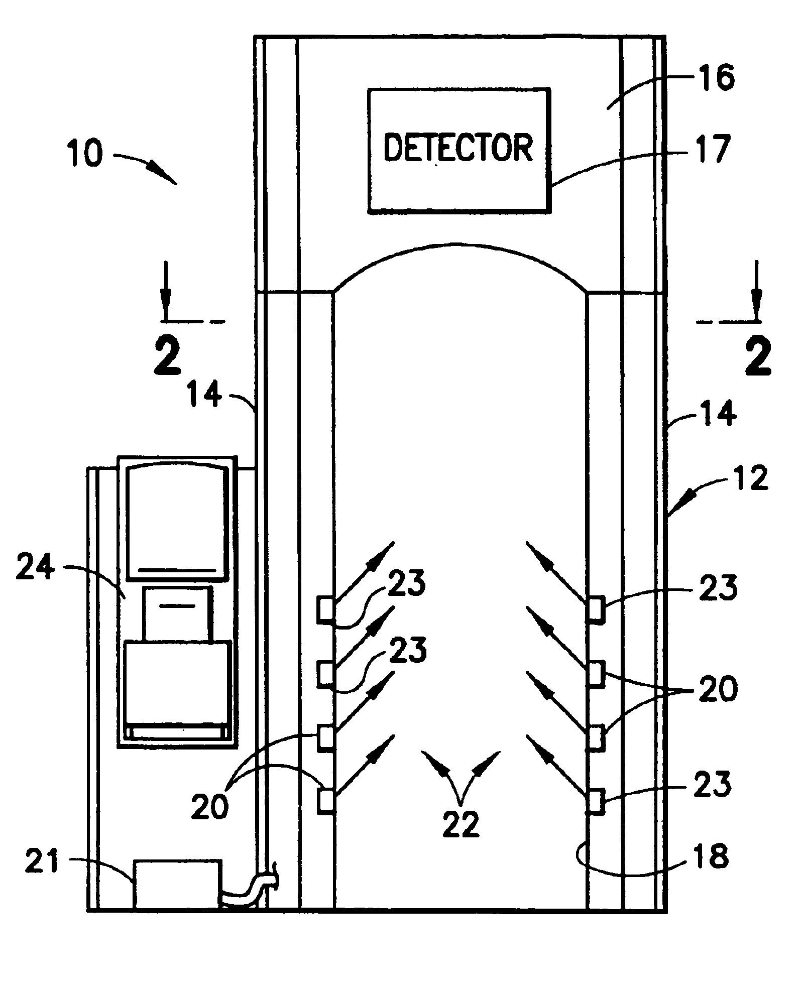
A portal detection system in accordance with the subject invention is identified generally by the numeral 10 in FIGS. 1 and 2. The portal detection system 10 is similar to the portal detection system disclosed in U.S. Pat. No. 6,073,499. In particular, the portal detection system 10 includes a portal 12 having a plurality of sidewalls 14, a plastic ceiling or hood 16 and a passage 18 extending between the sidewalls 14 and beneath the ceiling 16. The ceiling 16 preferably is made from or coated with an anti-static material such as KYDEX T as manufactured by Kleerdex. The anti-static material reduces or eliminates the electrostatic accumulation of particles of interest on the ceiling, and hence improves sensitivity. The ceiling 16 includes an inlet with a fan for producing an air flow that substantially matches the air flow rate provided by the human thermal plume. The ceiling 16 further includes at least portions of detection system 17. The detector of the subject invention is not di...


PUM


Abstract

A portal trace detection apparatus is provided for detecting minute particles of interest, such as traces of narcotics, explosives and other contraband. The apparatus includes a portal through which a human suspect will pass. A detection apparatus is disposed at least partly in the ceiling of the portal, and hence above the human subject in the portal. Particles of interest will be entrained in the human thermal plume that exists in the boundary layer of air adjacent the suspect, and will flow upwardly from the suspect to the detection apparatus in the ceiling of the portal. The portal includes a plurality of vertically aligned arrays of air jets. The air jets are fired sequentially from bottom to top to produce short bursts of air sufficient to disturb the clothing of the suspect and to dislodge particles of interest from the clothing. The dislodged particles of interest are entrained in the air in the human thermal plume and are transported upwardly to the detector.

Description

BACKGROUND OF THE INVENTION1. Field of the InventionThe subject invention relates to a detection apparatus for dislodging particles from clothing and skin of a person and then testing the dislodged particles for the presence of substances of interest.2. Description of the Related ArtDetection systems exist for detecting traces of materials, such as narcotics and explosives. Such systems are marketed by Ion Track Instruments, Inc. and are shown, for example, in U.S. Pat. No. 5,491,337.Prior art detection systems rely upon the fact that trace amounts of contraband will be transferred to the body of a person who handled the contraband, and subsequently will be transferred from the body to any article that the person may carry. These trace amounts of contraband may be collected for analysis by wiping a small sheet of appropriate material across a purse, suitcase or other article that has been handled by a suspect. The prior art sheet then is inserted into a prior art detection apparatus...

Claims


Application Information

Patent Timeline
IPC IPC(8): G01N1/22G01N1/02G01N15/00G01N1/24
CPCG01N1/2202G01N1/24G01N2015/0046G01N2001/2223G01N2001/024
Inventor JENKINS, ANTHONYMCGANN, WILLIAM J.PERRY, KEVIN J.
Owner RAPISCAN SYST INC (US)
Why Eureka
Try Eureka