Direct injection diesel engine

a diesel engine and direct injection technology, applied in the direction of combustion engines, electric control, pistons, etc., can solve the problems of not working effectively, restricting the temperature at which dpf or nox catalysts of the continuous regeneration type can be effective, and attracting attention

Inactive Publication Date: 2005-01-11
ISUZU MOTORS LTD
View PDF15 Cites 37 Cited by
  • Summary
  • Abstract
  • Description
  • Claims
  • Application Information

AI Technical Summary

Benefits of technology

[0020]In this way, since the fuel is injected in the radially outer direction from the lowermost position of the cavity in the conventional injection mode, fuel can be injected into the interior of the cavity both in the conventional injection mode and in the homogenious charge compression injection mode, making it possible to prevent fuel from adhering to the side wall within the cylinder in the homogenious charge compression injection mode and also preventing fuel accumulation in the vicinity of this lowermost position. Thereby, discharge of unburnt HC can be prevented.

Problems solved by technology

However, DPF or NOx catalysts of the continuous regeneration type, which have recently been attracting attention, are restricted in regard to the temperature at which they function effectively; in particular, they have problems such as not functioning effectively in the region of low / medium engine load, where the temperature of the engine exhaust gas is low.
Also, in the case of the above DPF or catalysts, when the reducing agent HC is added from the fuel, this is accompanied by a deterioration of fuel consumption.
However, retarding the fuel injection timing always results in a timing wherein the combustion period departs from the top dead center such that deterioration of thermal efficiency is difficult to avoid, and it is therefore undesirable since this is accompanied by deterioration of fuel consumption.
First of all, homogenious charge compression ignition combustion cannot be performed in all operating regions of the engine. This is because higher rates of fuel injection under full load result in ignition starting before the engine reaches the vicinity of the top dead center, resulting in severe knocking, which damages the engine. Another reason is that even if ignition starts in the vicinity of the top dead center, subsequent combustion proceeds all at once, resulting in a rise in combustion temperature and increased NOx.
Next, in homogenious charge compression ignition combustion, since the fuel is injected when the piston is lower than normal, if the injection angle is not correctly set, the fuel that is injected sticks to the inside wall of the cylinder, tending to cause an increase in unburnt HC and / or oil dilution, which tends to result in a deterioration in fuel consumption.

Method used


Image

  • Direct injection diesel engine
  • Direct injection diesel engine

Examples


Embodiment Construction

[0025]A preferred embodiment of the present invention is described below with reference to the accompanying drawings.

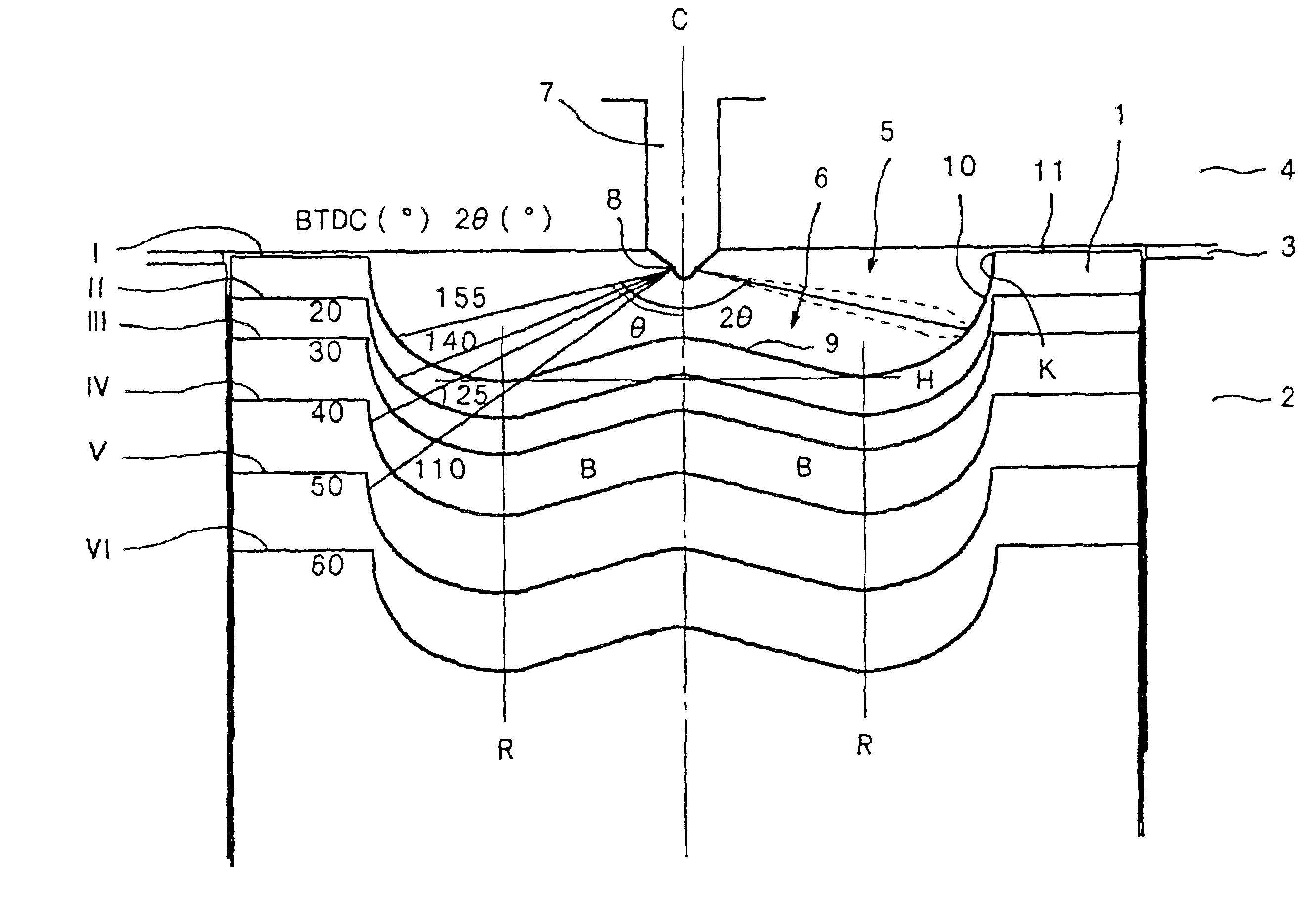
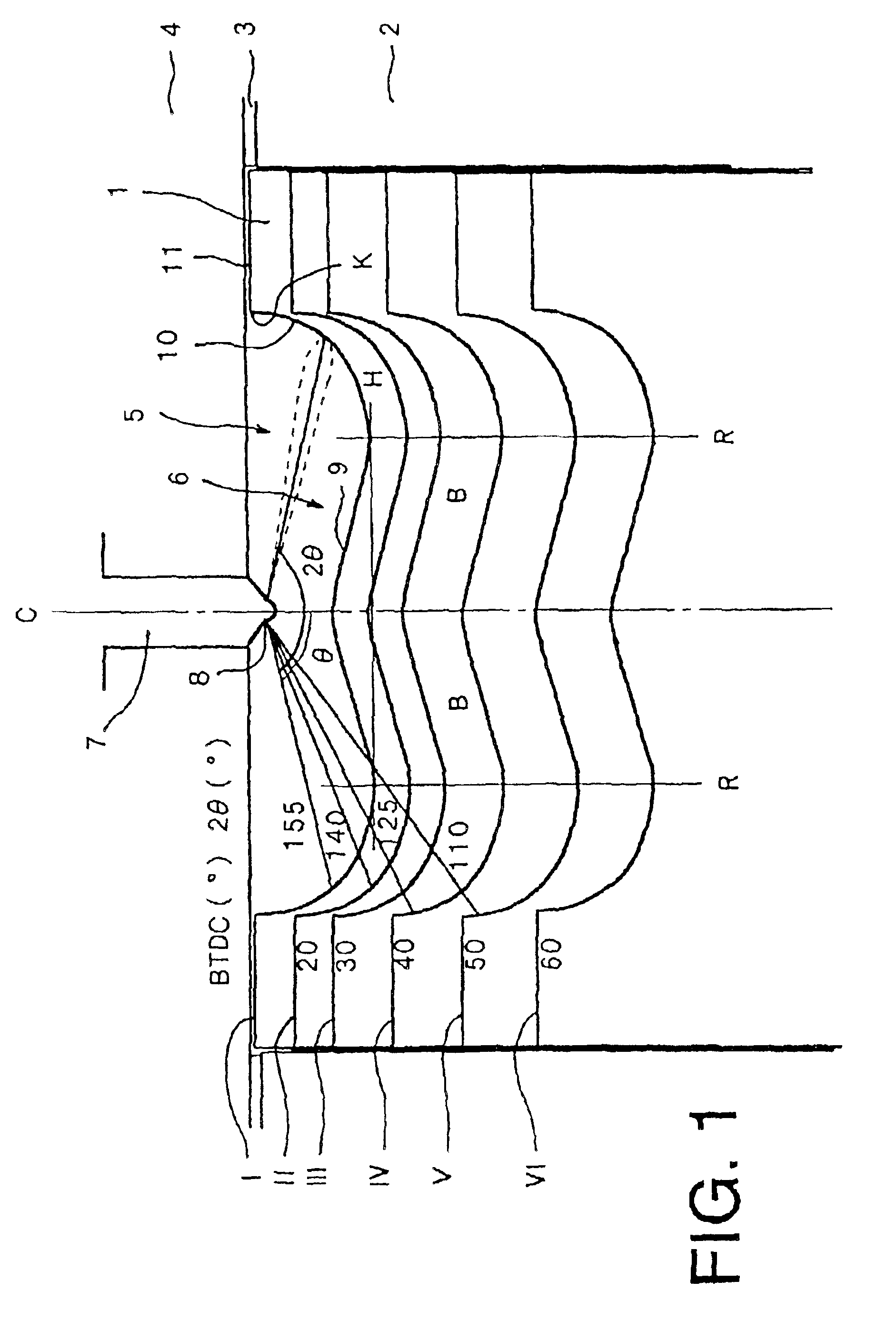
[0026]FIG. 1 is a cross sectional view showing the interior of a direct injection diesel engine according to this embodiment. As shown in the Figure, a cylinder head 4 is mounted with the aid of a gasket 3 at the top of a cylinder 2, piston 1 being provided so as to be free to reciprocate vertically within cylinder 2. A combustion chamber 5 is defined by this piston 1, cylinder 2 and cylinder head 4. A cavity 6 is provided at the top of piston 1; cavity 6 defines part of combustion chamber 5. A fuel-injection nozzle 7 for injecting fuel into combustion chamber 5 is provided in cylinder head 4. The tip of fuel-injection nozzle 7 projects into the interior of the combustion chamber 5 and a plurality of jets 8 are provided at its tip.

[0027]The axes of piston 1, cylinder 2, fuel-injection nozzle 7 and cavity 6 are arranged on the same axis C. These are therefore all arran...


PUM


Abstract

Cleaning of exhaust gas and reduction of fuel costs are aimed at while realizing homogenious charge (or pre-mixing) compression ignition combustion and performing fuel injection in a suitable manner in all regions of engine operation. In a direct injection diesel engine there are provided an conventional injection mode in which fuel is injected with a timing (I) in the vicinity of the compression top dead center of piston (1) and a homogenious charge compression injection mode in which fuel is injected with a timing (II to V) which is earlier than that in the conventional injection mode, and such that fuel ignition does not occur at least until injection has been completed, fuel injection being performed by the conventional injection mode during full load operation of the engine and fuel injection being performed by the homogenious charge compression injection mode during part (low/medium) load operation of the engine. Ordinary diffusion combustion is realized when operating the engine under full load yet while receiving the benefit of amelioration of exhaust gas etc due to homogenious charge compression ignition combustion; thus, suitable fuel injection can be implemented over the entire operating range.

Description

CROSS REFERENCES TO RELATED APPLICATIONS[0002]This application is entitled to the benefit of and incorporates by reference essential subject matter disclosed in Japanese Patent Application No. 2001-272141 filed Sep. 7, 2001.BACKGROUND OF THE INVENTION[0003]1. Field of the Invention[0004]The present invention relates to a direct injection diesel engine and in particular relates to a direct injection diesel engine wherein the cleaning of exhaust gas and improvement in fuel consumption are effected by performing homogenious charge compression ignition combustion.[0005]2. Description of the Related Art[0006]In recent years, demands for environmental measures relating to internal combustion engines, in particular diesel engines, have become increasingly strong and various means such as diesel particulate filters (DPF) that capture soot such as black smoke or NOx catalysts that effect cleaning by reducing NOx are being provided. In addition, various combustion systems are being studied in...

Claims


Application Information

Patent Timeline
Patent Type & Authority Patents(United States)
IPC IPC(8): F02B23/06F02B23/02F02B1/12F02D41/40F02D41/30F02B1/00F02B3/06F02B3/00F02D41/04F02D45/00F02F3/26
CPCF02B1/12F02B23/0696F02D41/3035F02D41/401Y02T10/123F02B23/0621F02B23/0624F02B23/0651F02B23/0669F02B2275/14F02D41/3076F02D2041/389Y02T10/125Y02T10/128Y02T10/44F02B3/06Y02T10/12Y02T10/40
Inventor SHIMAZAKI, NAOKI
Owner ISUZU MOTORS LTD
Why Eureka
Try Eureka