Accumulator for elongated products, such as tubes and the like

a technology of accumulators and products, applied in the field of accumulators or storage units, can solve the problems of affecting the efficiency of rewinding machines, and affecting the efficiency of rewinding machines, and achieve the effect of moderate flexural resistan

Inactive Publication Date: 2005-01-11
FABIO PERINI SPA
View PDF7 Cites 16 Cited by
  • Summary
  • Abstract
  • Description
  • Claims
  • Application Information

AI Technical Summary

Benefits of technology

The object of the present invention is to create an accumulator for temporarily accumulating elongated products—specifically, but not exclusively winding tubes or tubular cores, e.g. made of cardboard, for the production of rolls of ribbon-shaped material—which overcomes the shortcomings of the storage units known in current art and permits the handling of products which may also be very long and present modest flexural resistance.
In this way, the accumulator is particularly suitable for handling long and light objects. The accumulator particularly lends itself for handling tubular winding cores which are temporarily stored, holding them reciprocally separate, avoiding twisting and consequent damage. The possibility of having objects which extend between the flexible member and the guide wheel is exploited to arrange the flexible members and the respective supports in intermediate positions along the axial development of the products. In this way, intermediate rests are provided along the products, without the need for continuous oscillating support elements, which are at least as long as the products themselves, as in the case of accumulators which are traditionally used for rolls.
The result is a light-weight, compact and cost-effective accumulator, suitable also for supporting objects such as tubular cardboard cores of high length and modest flexural resistance.
The radial arms may advantageously present a tapered intermediate area so to provide a large space for the products accumulated in the accumulator in order to leave a sufficient space for the passage of products without excessively reducing the contact surface between the wheel and the flexible member. Conversely, the outermost radial end of each of the radial arms presents a development in the tangential direction which is higher than the width in said intermediate tapered area, so to increase the contact surface with the flexible member, i.e. the number of teeth in the case in which the flexible member is a chain.
Having reduced the contact area between the flexible member and the wheels equipped with radial arms to the end of the radial arms themselves, a slight vibration is induced. This is due to the fact that the contact surface between the flexible member and the wheel is not uniform and continuous and that the flexible member is arranged with a polygonal configuration on the guide wheel. To reduce this vibration, it is advantageous to provide that the radial arms of the various wheels are angularly and reciprocally displaced. Particularly, the radial arms of the wheels which are on the same axis can be angularly displaced. For example, if the accumulator presents four flexible members developed along four closed paths lying on an equal number of reciprocally parallel planes, a contoured guide wheel with radial arms allowing the passage of the product between the flexible member and the wheel will be provided. All these wheels will be aligned on the same axis. The wheels can be reciprocally displaced, e.g. by one chain link or less. In this way, the contact between the radial arms of the single wheels and the various flexible members is not simultaneous for all flexible members, whereby reducing the vibrations totally transmitted to the accumulator structure. Since the supports are angularly timed with the radial arms of the wheels, this angular displacement of the radial arms causes a slight displacement also of the supports. Consequently, each product rests on a set of supports, e.g. on four supports, aligned along a line which, is slightly slanted instead of being perfectly horizontal. This is, however, perfectly acceptable.

Problems solved by technology

It has bead that very long cores tend to assume irregular positions in the currently employed accumulators and even present the tendency to twist one on the other and consequently break, jamming the automatic flow to the rewinder.
This entails considerable production problems.
Similar problems may occur in other sectors in which elongated shape products, specifically products with modest flexural resistance, are accumulated and held in an accumulator.
This type of accumulator is not suitable for handling elongated light objects with small transversal dimensions (such as winding tubes or cores) due to the need to arrange costly and cumbersome oscillating supports which increase the cost of the accumulator.

Method used


Image

  • Accumulator for elongated products, such as tubes and the like
  • Accumulator for elongated products, such as tubes and the like
  • Accumulator for elongated products, such as tubes and the like

Examples


Embodiment Construction

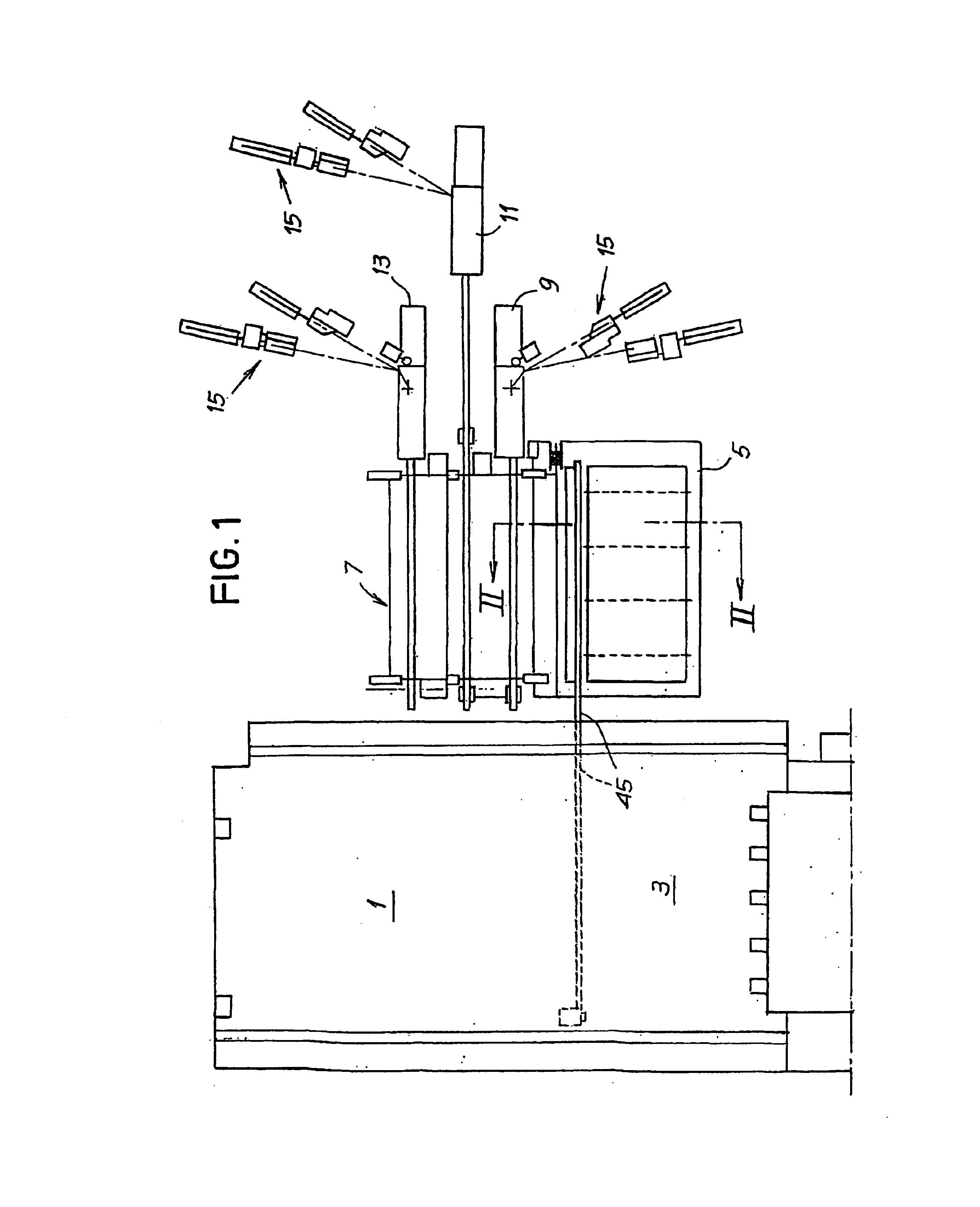
FIG. 1 very roughly outlines a layout of a paper converting system for the production of rolls or logs of weblike material. Reference numeral 1 generally indicates the area where the unwinders of the parent rolls, which supply the weblike material, are arranged. Reference numeral 3 indicates the area where the rewinder is located. Other stations (not shown) are arranged downstream to the rewinder, typically one or more glue application machines, a roll accumulator, one or more saw machines and packaging machines.

An accumulator for winding cores, generally indicated with reference numeral 5, which will be described in detail below, is arranged by the side of the area 1, 3 occupied by the unwinders and the rewinder. Reference numeral 7 indicates the outline of a conveyor which supplies the cores to the accumulator 5. The cores are made (in the example shown) by three tube making machines 9, 11, 13, supplied by rolls of ribbons of cardboard 15. It is clear that a different number of tu...


PUM


Abstract

The accumulator (5) comprises at least two continuous flexible members (55) equipped with supports (57) for the products (A). The supports (57) project laterally with respect to the respective flexible member; each flexible member and at least one first guide wheel (63A) being arranged so that the supports face the axis of the wheel in the section of flexible member trained about said guide wheel. The guide wheel is equipped with a plurality of radial arms between which a space is provided for the elongated products resting on said supports. The position of the supports is timed with respect to the position of the radial arms.

Description

FIELD OF THE INVENTIONThe present invention relates to an accumulator or storage unit for temporarily accumulating elongated products, such as tubes or the like, comprising at least two continuous flexible members developing each along a respective closed path defined by a plurality of guide wheels, the paths defined by said flexible members being reciprocally parallel, and in which said flexible members are equipped with supports for the elongated products.Particularly, but not exclusively, the accumulator may be used for cardboard tubes intended for the production of rolls of plastic film, of papers, such as toilet paper, kitchen paper or other items made of tissue paper and the like.BACKGROUND OF THE INVENTIONIn many industrial fields, filiform or web-shaped materials are wound on tubular winding cores made of plastic, cardboard or other material. These tubular winding cores (hereof also simply called “cores”) are accumulated in a storage unit and gradually supplied to the machin...

Claims


Application Information

Patent Timeline
Patent Type & Authority Patents(United States)
IPC IPC(8): B65G17/30B65G17/46B65G47/51
CPCB65G17/46B65G47/5122B65G2201/02
Inventor BETTI, GIULIOBENVENUTI, ANGELODI NARDO, WALTER
Owner FABIO PERINI SPA
Why Eureka
Try Eureka