Electrofusion joint

a technology of fusion joint and collar portion, which is applied in the direction of hose connection, branching pipe, mechanical apparatus, etc., can solve the problems of reducing fusion welding strength, lowering interface pressure, and difficult to fit the saddle portion on the main pipe, so as to improve the contact closeness and increase the flexure of the collar portion

Inactive Publication Date: 2005-01-11
MITSUI CHEM IND PROD
View PDF25 Cites 10 Cited by
  • Summary
  • Abstract
  • Description
  • Claims
  • Application Information

AI Technical Summary

Benefits of technology

An object of the present invention is to provide an electrofusion joint comprising a saddle portion that can achieve an improved contacting closeness with the lateral portions of the circumferential surface of a main pipe, by increasing flexure of a collar portion when it is clamped, even though rigidity of the saddle portion is large or the distance from a spigot or trunk portion projecting from the saddle portion to the collar portion is short.
According to the invention, since the recess can prolong the distance from the spigot or trunk portion to the collar portion, a larger flexure of the collar portion can be attained when the saddle portion is clamped with a main pipe by engaging a latch of a clamping device with the collar portion even though rigidity of the saddle portion is large or the diameter of the spigot or trunk portion projecting from the saddle portion is large, and as a result the seating surface of the saddle portion can make close contact with the main pipe. Also, the wall thickness of the saddle portion can be made thicker to prevent deformation of the saddle portion at the fusion welding, thereby a reduction in fusion welding strength due to a fall in interface pressure can be prevented.
According to the invention, by forming the saddle portion of an appropriate wall thickness contacting closeness, with the main pipe is improved, therefore bubbles at the fusion welding interface and short circuits due to mutual contact of the heating wires can be minimized, and a sufficient fusion welding strength can also be achieved since a fall in interface pressure by deformation of the saddle portion can be prevented.
As a result, the advantages of aforementioned aspects of the invention can be enhanced further.

Problems solved by technology

Otherwise, bubbles may be formed in the fusion welding interface during the electrofusion welding process, or the heating wires may move and contact each other to cause a short circuit.
However, since the joint is a molded product, it is difficult to mold it in such a manner that the seating surface of the saddle portion can achieve close contact with outer circumferential surface of the main pipe, and even if such precise molding is accomplished it will be difficult to fit the saddle portion on the main pipe by pressing the joint onto the main pipe from a lateral direction, if rigidity of the saddle portion is too large.
However, on the other hand, heat generated from heating wires through electric conduction is transferred to the outer surface if the saddle portion, and as a result the saddle portion tends to deform, resulting in lowered interface pressure and consequently in reduced fusion welding strength.
On one side, if rigidity of the saddle portion is large, it can hardly be bent by clamping, and if the diameter of the spigot or trunk portion projecting from the saddle portion is large and the distance from the spigot or trunk portion to the collar portion is relatively short, the extent of possible flexure of the collar portion will be limited, resulting in inferior contact closeness with the outer circumferential surface of the main pipe.

Method used


Image

  • Electrofusion joint
  • Electrofusion joint
  • Electrofusion joint

Examples


Embodiment Construction

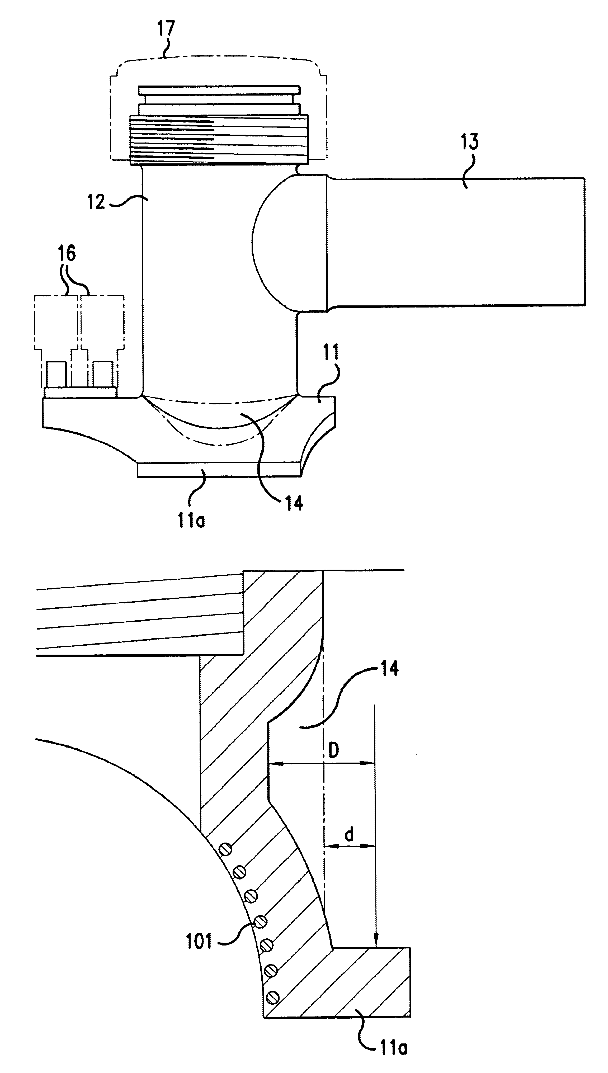
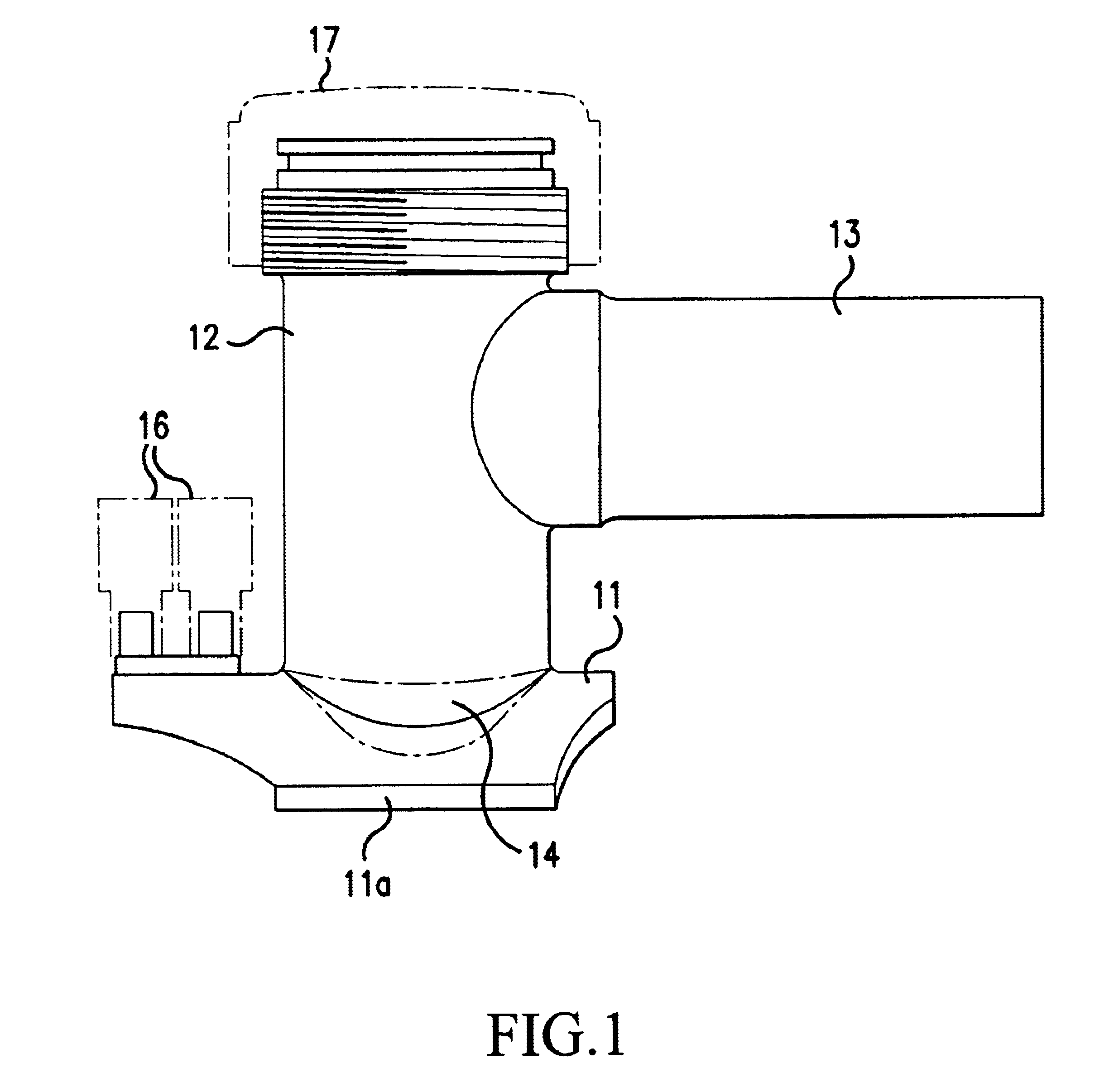
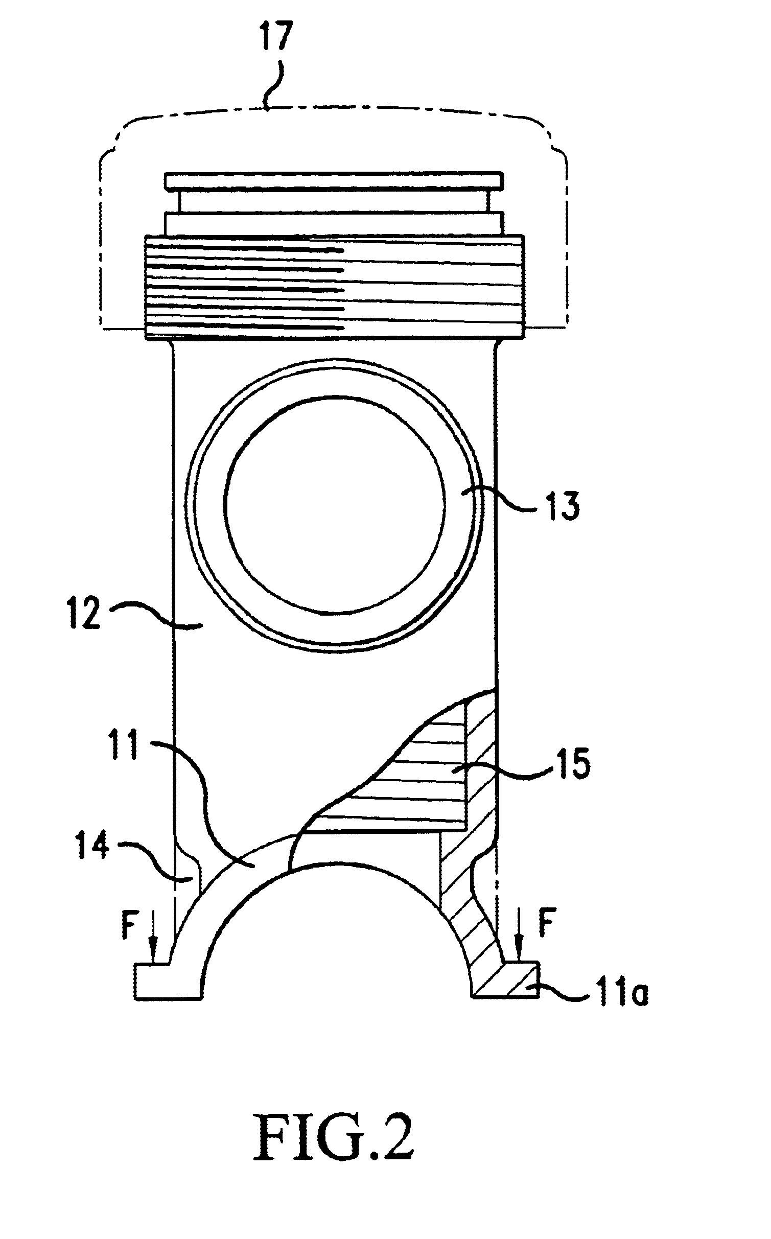
FIG. 1 and FIG. 2 show a service tee joint, comprising a saddle portion 11 provided with heating wires 101 (See FIGS. 3 and 6) embedded in its seating surface to be joined to a resin pipe and a collar portion 11a on its both sides; a trunk portion 12 projecting from saddle portion 11 and into which a hole saw that is not shown is to be screwed; and a spigot 13 projecting in a lateral direction from trunk portion 12 and to which a branch pipe is to be connected; and a recess 14 is formed by denting a certain range on the collar portion side along the base of the trunk portion projecting from saddle portion 11, or outside a small diameter portion where the tip of a hole saw is engaged at the bottom of threaded portion 15 into which a hole saw is screwed.

Referring to FIG. 1 and FIG. 2, reference number 16 indicates a terminal to which connectors of the controller for electrofusion welding not shown are inserted, and number 17 indicates a cap screwed over the upper end of the trunk port...


PUM

PropertyMeasurementUnit
thicknessaaaaaaaaaa
thicknessaaaaaaaaaa
wall thicknessaaaaaaaaaa

Abstract

The invention provides an electrofusion joint made of a thermoplastic resin for connection with a resin pipe by heat generation of heating wires embedded in its saddle portion through electric conduction, such as a saddle joint comprising a saddle portion to be fitted to an outer circumferential surface of a resin pipe provided with heating wires embedded in its surface to be joined to the resin pipe, also comprising a spigot projecting from the saddle portion and to which a branch pipe is to be connected, or a service tee joint comprising a saddle portion in which heating wires are embedded, a trunk portion projecting from the saddle portion and a spigot projecting in a lateral direction from the trunk portion. A recess is formed in a part on the collar portion side along the base of the spigot of the saddle joint or trunk portion of the service tee joint, to increase the length from the recess to the collar portion where a latch of a clamping device is engaged, so that the collar portion becomes sufficiently flexible to achieve closer contact with the pipe and to prevent defective fusion welding, even though wall thickness or rigidity of the saddle portion is large.

Description

BACKGROUND OF THE INVENTION1. Field of the InventionThe present invention relates to an electrofusion joint for connecting a branch pipe with a main pipe made of a thermoplastic resin, particularly to an electrofusion joint provided with a saddle portion such as a saddle joint or service tee joint, to be joined at the outer circumferential surface of a main pipe.2. Description of the Related ArtFIG. 5 is a side view of a saddle joint comprising saddle portion 1 and spigot 2 to which a branch pipe is to be connected, and which is generally made of a mold of medium density or high density polyethylene. As shown in the drawing, for electrofusion welding with a main pipe 3 made of a thermoplastic resin, the seating surface of the saddle portion is placed on the outer circumferential surface of the main pipe, and after clamping collar portion 4 on both sides of the saddle portion by engaging a latch of a clamping device that is not shown provided at the opposite side (lower side of FIG. ...

Claims


Application Information

Patent Timeline
Patent Type & Authority Patents(United States)
IPC IPC(8): B29C65/34F16L47/28F16L47/00F16L47/02F16L47/03F16L41/06
CPCB29C65/342F16L47/03B29C66/131B29C65/3476B29C66/52241B29C66/5229B29C66/112F16L47/28B29K2023/06B29K2023/0641B29K2023/065B29C65/3468B29C66/71
Inventor TANAKA, HIROAKIIWASAKI, MASAYA
Owner MITSUI CHEM IND PROD
Why Eureka
Try Eureka