Release mechanism

a technology of release mechanism and axial length, which is applied in the direction of fluid actuated clutches, non-mechanical actuated clutches, clutches, etc., can solve the problems of increasing so as to shorten the axial length of the release mechanism and increase the outside diameter of the bearing. , the effect of shortening the axial length

Inactive Publication Date: 2016-06-09
TOYOTA JIDOSHA KK
View PDF8 Cites 0 Cited by
  • Summary
  • Abstract
  • Description
  • Claims
  • Application Information

AI Technical Summary

Benefits of technology

[0014]According to the release mechanism of the one aspect of the present invention, the bearing is placed so as to make contact with the diaphragm spring configured to press the pressure plate against the clutch disc, so that the load in the direction in which the pressure plate is separated from the clutch disc is transmitted from the bearing. Further, the bearing is configured such that a load caused by the hydraulic actuator and a spring force of the return spring are applied to the bearing. Further, the hydraulic actuator, the bearing, and the return spring are placed so as to overlap with each other in the radial direction of the output-side rotational member. This makes it possible to shorten an axial length of the release mechanism configured to separate the pressure plate from the clutch disc. Further, the bearing and the return spring are provided on an outer peripheral side relative to the hydraulic actuator, and the bearing makes contact with the diaphragm spring. This makes it possible to restrain or prevent a non-movable portion such as a cylinder constituting the hydraulic actuator from making contact with a ...

Problems solved by technology

This may increase the axial length of the release mechanism.
Accordingly, when the rigidity of such me...

Method used


Image

  • Release mechanism
  • Release mechanism
  • Release mechanism

Examples


Embodiment Construction

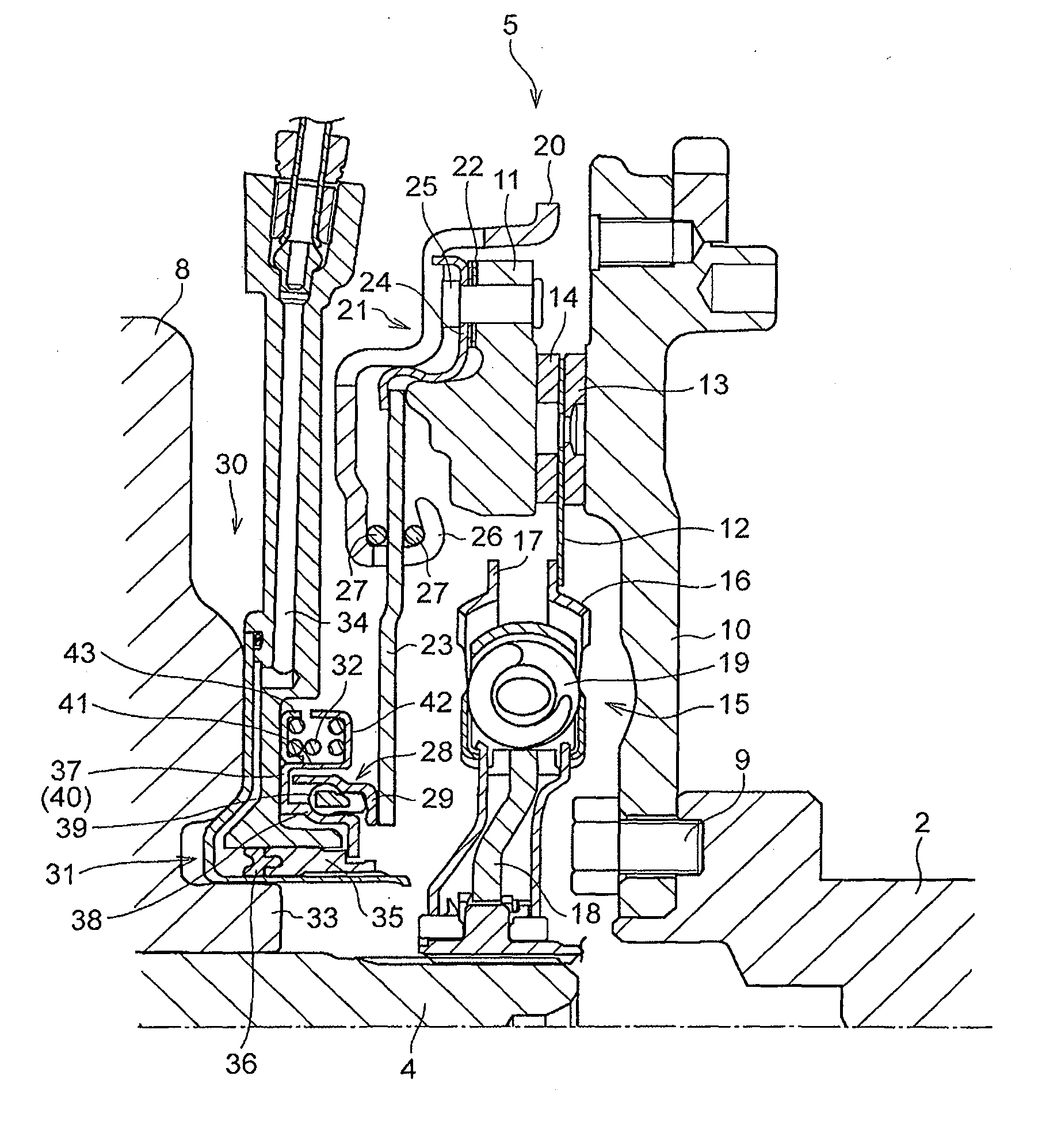
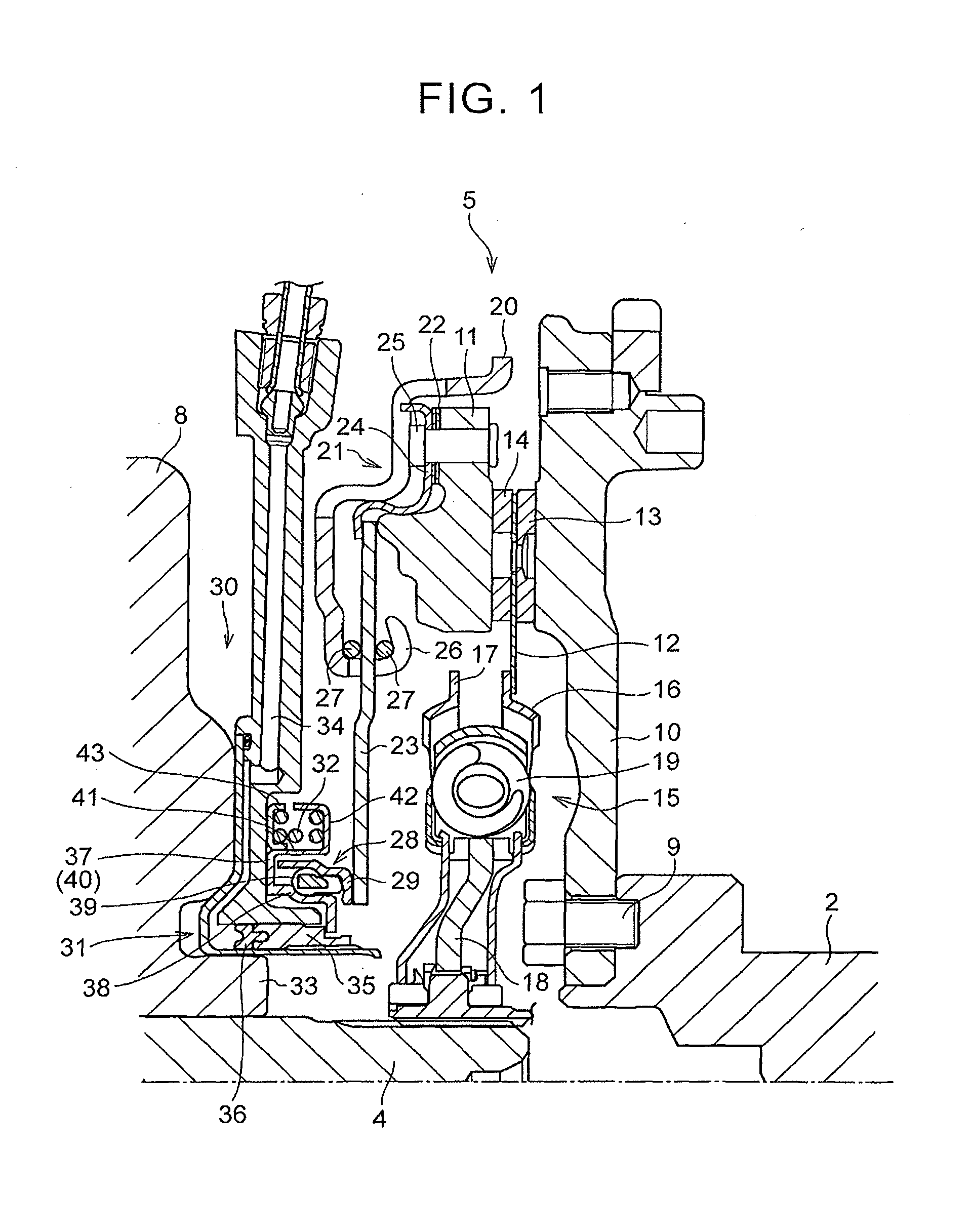
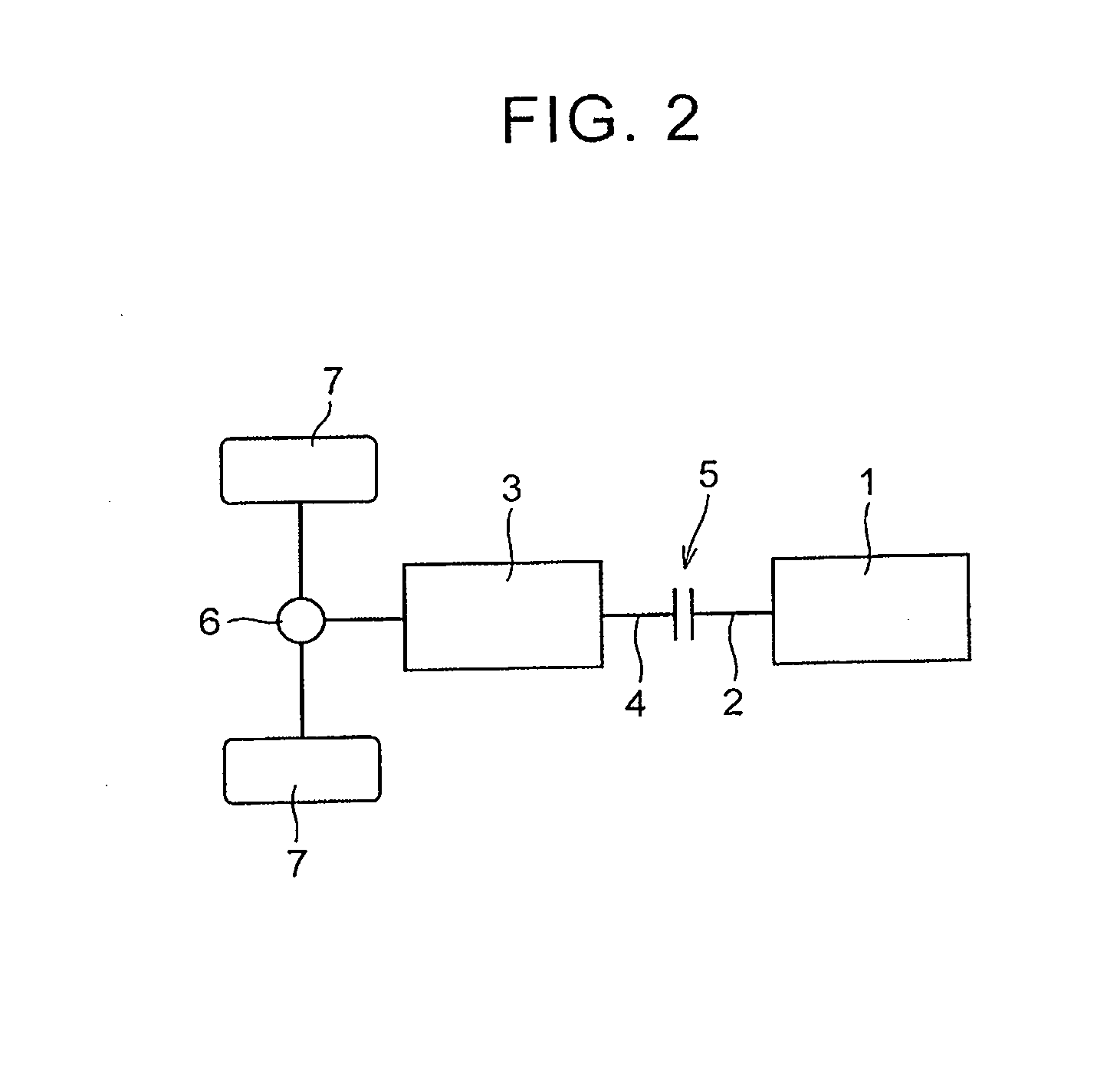
[0019]A clutch of the present invention is configured such that, when a pressure plate configured to rotate integrally with an input-side rotational member is pressed by a clutch disc connected to an output-side rotational member, the input-side rotational member is connected to the output-side rotational member in a torque transmittable manner. The clutch configured as such is configured to be released in such a manner that a load to separate the pressure plate from a clutch disc is applied to the clutch to decrease a frictional force. FIG. 2 schematically illustrates an example of a gear train of a vehicle including the clutch configured as such. The gear train illustrated in FIG. 2 is provided in a vehicle front side, and is mounted in a front-engine front-drive vehicle configured such that a torque is transmitted to front wheels. Further, the vehicle illustrated in FIG. 2 is configured such that a clutch 5 is provided between a crankshaft 2 serving as an output shaft of an engin...


PUM


Abstract

A release mechanism includes a clutch, a bearing, a hydraulic actuator, and a return spring. The clutch transmits a torque between an input-side rotational member and an output-side rotational member by pressing the pressure plate against a clutch disc by an elastic force of a diaphragm spring. The bearing transmits a load in a direction in which a pressure plate is separated from the clutch disc. The bearing is placed on an outer peripheral side of the hydraulic actuator in a radial direction of the output-side rotational member. The hydraulic actuator transmits, to the bearing, a load to separate the pressure plate from the clutch disc. The return spring, the hydraulic actuator, and the bearing are placed so as to overlap with each other in an axis direction of the output-side rotational member. The return spring is placed on an outer peripheral side of the bearing.

Description

BACKGROUND OF THE INVENTION[0001]1. Field of the Invention[0002]The present invention relates to a release mechanism configured to release a clutch in such a manner that a thrust according to a hydraulic pressure supplied to a hydraulic actuator is applied to a diaphragm spring so that the diaphragm spring decreases a load to press a pressure plate against a clutch disc.[0003]2. Description of Related Art[0004]There has been known a clutch that enables torque transmission between an input-side rotational member and an output-side rotational member by sandwiching a clutch disc connected to the output-side rotational member between a pressure plate connected to an outer peripheral side of a diaphragm spring and the input-side rotational member. A release mechanism configured to release the clutch configured as such is configured to release the clutch by pressing an inner peripheral portion of the diaphragm spring so that the diaphragm spring decreases a load to press the pressure plat...

Claims


Application Information

Patent Timeline
IPC IPC(8): F16D25/08F16D13/58F16D13/40
CPCF16D25/087F16D13/583F16D13/40F16D25/083F16D23/14
Inventor HATA, KENSEIIWASE, YUJISUZUKI, YOSUKEKATO, KOICHINOBUYASU, SEITAROMOTEKI, TARO
Owner TOYOTA JIDOSHA KK
Why Eureka
Try Eureka