Quick connection for the removable join of pipes

a technology of removable joins and pipes, applied in the field of quick connections, can solve the problems of effective manual operation and difficulty in connecting the above-mentioned types, and achieve the effect of convenient movemen

Inactive Publication Date: 2005-01-11
STAUBLI FAVERGES SA
View PDF20 Cites 56 Cited by
  • Summary
  • Abstract
  • Description
  • Claims
  • Application Information

AI Technical Summary

Benefits of technology

Thanks to the invention, the downstream pipe may be drained of the fluid that it contains, while the male connector is in abutment on the intermediate tooth, with the result that, when this draining operation is terminated, the pressure prevailing in the downstream pipe is substantially equal to the ambient pressure and the shoulder does not exert a considerable effort on the intermediate tooth, this allowing the bolt to be easily moved.
According to advantageous but non-obligatory aspects of the invention, this connection incorporates one or more of the following characteristics:The afore-mentioned communicating means comprise at least one orifice formed in the body of the female element, downstream of the valve. This orifice may advantageously be obturated by the male element when the latter rests by its shoulder against the tooth most remote from the opening of a central conduit of the female element. In other words, this orifice is closed when the connection is in passing configuration. In addition, this orifice may be provided to extend in a direction which is substantially radial with respect to the axis of fit of the male and female elements.The communicating means are arranged in a zone of the body of the female element distinct from the part in which the bolt slides. Thanks to this aspect of the invention, the fluid coming from the downstream pipe does not risk disturbing slide of the bolt.The communicating means are arranged upstream of that part of the body of the female element in which the bolt slides.The female element is equipped with means adapted to ensure seal of the connection between the male and female elements, while, when it rests against the intermediate tooth, the male connector is disengaged with respect to the sealing means. In this way, the sealing means do not oppose the drain of the downstream pipe.

Problems solved by technology

However, when the male element is in abutment by its shoulder against the intermediate tooth, it exerts thereon an effort which depends on the pressure of the fluid present in the pipe connected to the male element.
In other words, a connection of the afore-mentioned type becomes difficult to make when it is used with a fluid at relatively high pressure.
Now, such a connection must be able to be used for fluid networks at 6 or 10 bars, and even 25 bars, in which case it is effectively difficult to accomplish manually.

Method used


Image

  • Quick connection for the removable join of pipes
  • Quick connection for the removable join of pipes
  • Quick connection for the removable join of pipes

Examples


Embodiment Construction

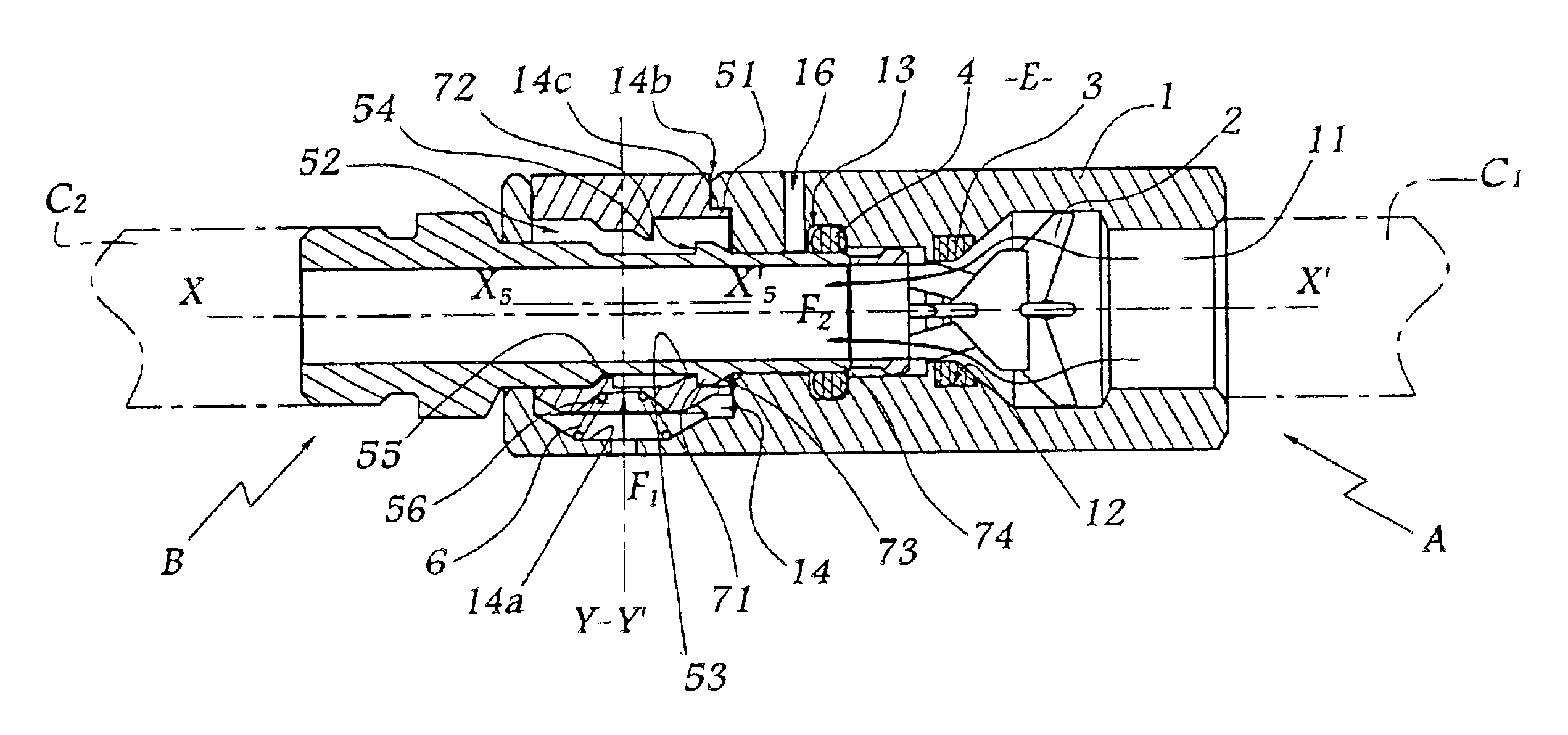
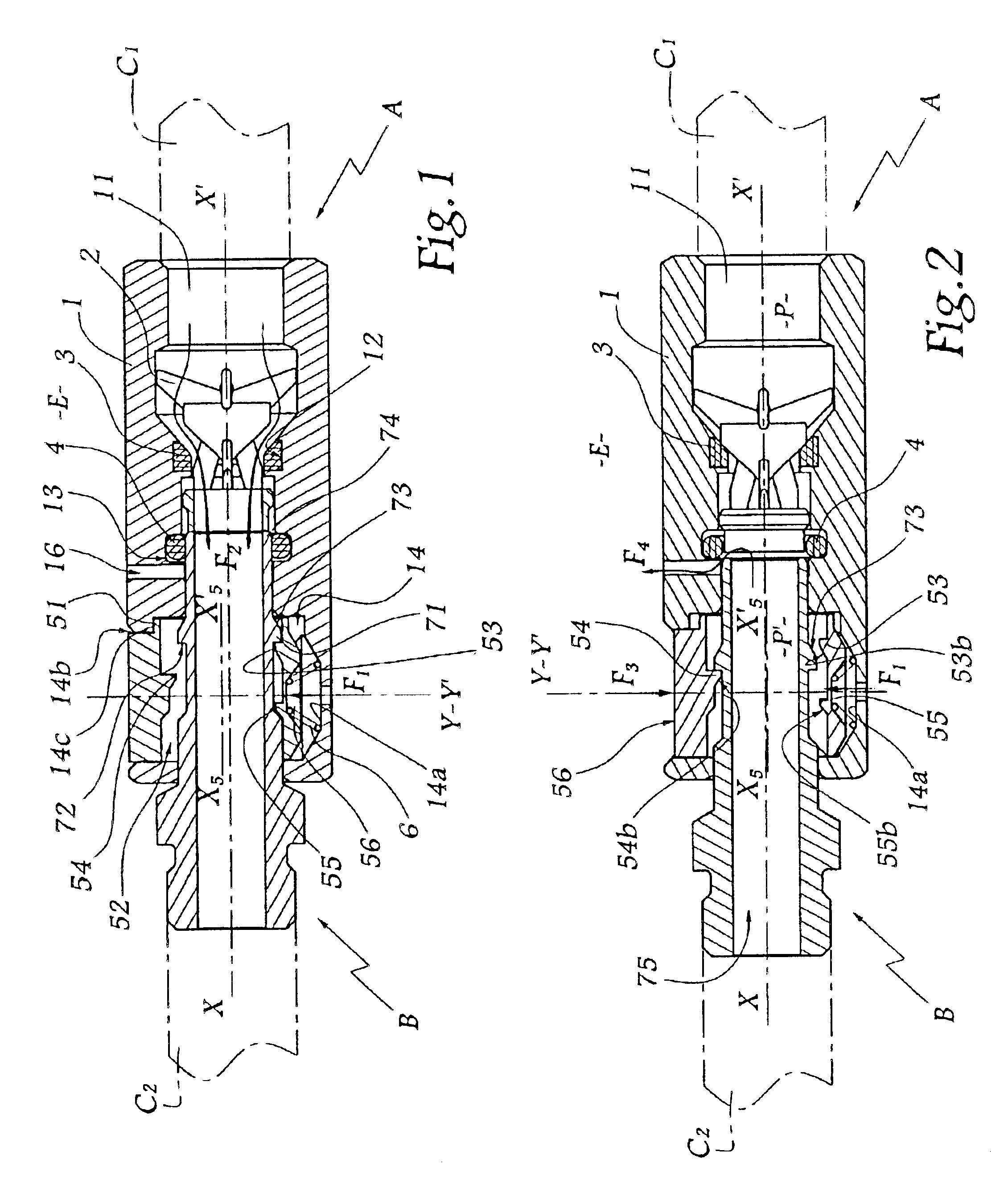
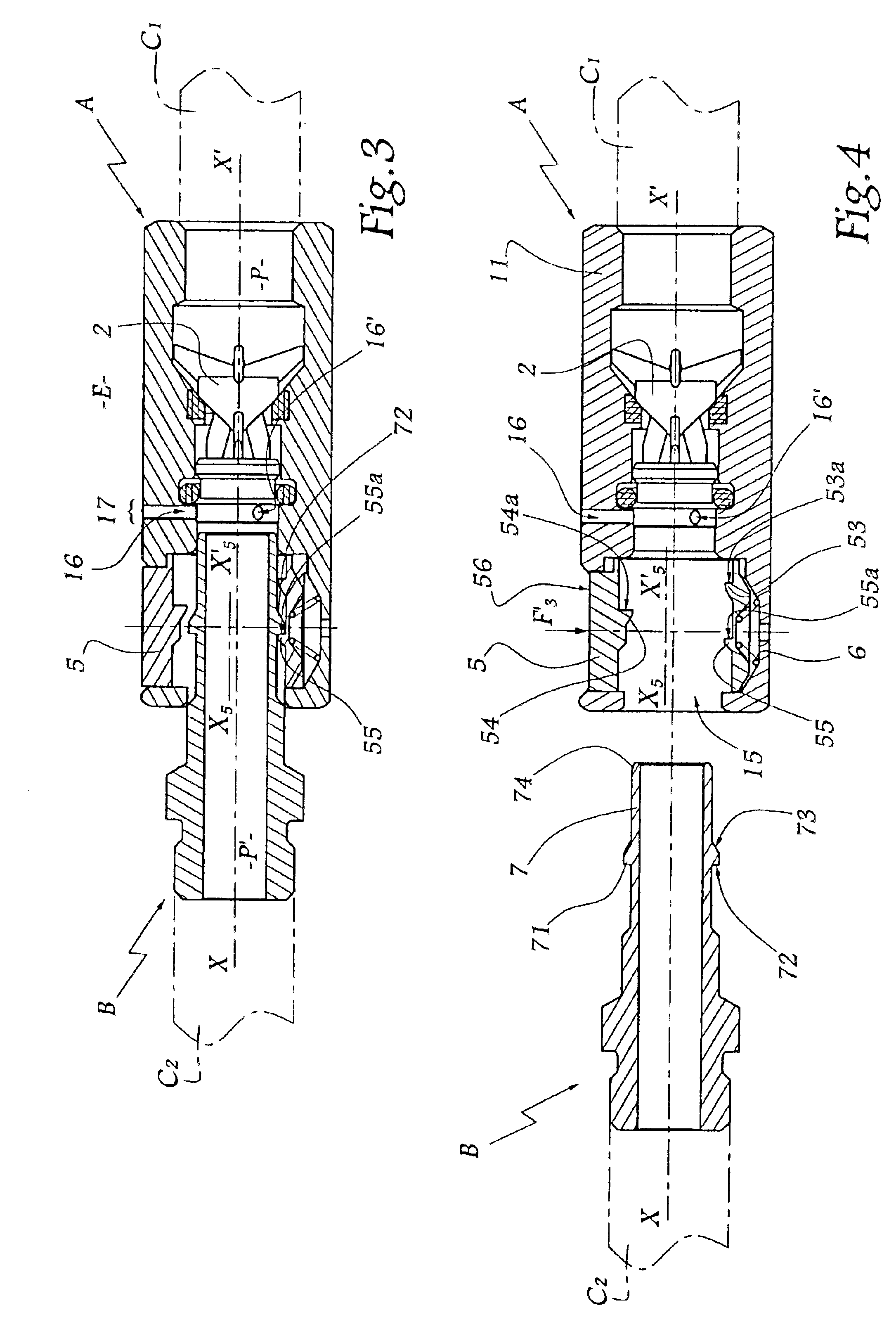
Referring now to the drawings, the connection shown in FIGS. 1 to 4 comprises a female element A and a male element or connector B connected respectively to an upstream pipe C1 and to a downstream pipe C2. The upstream pipe C1 is itself connected to a source of fluid under pressure (not shown).

The body 1 of the female element has a substantially cylindrical and circular outer shape, centered on an axis X-X′ which is also the longitudinal axis of a conduit 11, inside the body 1, and in which is disposed a valve 2 mobile along axis X-X′. The body 1 is also equipped with a seal 3 forming a seat for the valve and disposed inside a groove 12 made in the wall of the conduit 11.

The body 1 forms a second groove 13 for receiving an O-ring 4.

The body 1 is also provided with a cylindrical housing 14 extending substantially in the direction of an axis Y-Y′ perpendicular to axis X-X′.

Inside the housing 14 there is slidably mounted a bolt 5 on which a spring 6 exerts an elastic effort F1 directed...


PUM


Abstract

A quick connect coupling for joining two pipes which includes a male and a female element adapted to fit axially in each other. A body of the female element is equipped with a resiliently urged bolt mounted to slide in the body and provided with a central opening for receiving the male element. A wall of the opening is equipped with three teeth offset with respect to one another along a median axis of the opening. The male element is provided with a shoulder adapted to rest selectively against one of the teeth. When the male element rests against an intermediate tooth, a the downstream pipe is placed in communication with ambient atmosphere.

Description

BACKGROUND OF THE INVENTION1. Field of the InventionThe present invention relates to a quick connection for removably joining two pipes through which a pressurized fluid passes.2. Description of the Related ArtPatent FR 2 514 855 discloses a quick connection which comprises two elements, male and female, adapted to fit axially, provoking the opening of a valve mounted in the body of the female element, this body being equipped with a loaded bolt, mounted to slide in this body and pierced with a central opening for the fit of the male element. The wall of the opening of the bolt presents three teeth offset with respect to one another along a median axis of this opening, while the male element is provided with a shoulder adapted to rest selectively against one of these teeth. The movement of unlocking of this known connection takes place in two steps corresponding respectively to the abutment of the shoulder of the male element on the intermediate tooth and on the tooth nearest to the...

Claims


Application Information

Patent Timeline
Patent Type & Authority Patents(United States)
IPC IPC(8): F16L37/00F16L37/084F16L37/08F16L37/12
CPCF16L37/0841Y10S285/924F16L37/42F16L37/252
Inventor LACROIX, JEAN-JACQUES
Owner STAUBLI FAVERGES SA
Why Eureka
Try Eureka