
Rollout tray mounting system for cabinet

Inactive Publication Date: 2005-01-11
TENN TEX PLASTICS
View PDF23 Cites 4 Cited by
  • Summary
  • Abstract
  • Description
  • Claims
  • Application Information

AI Technical Summary

Benefits of technology

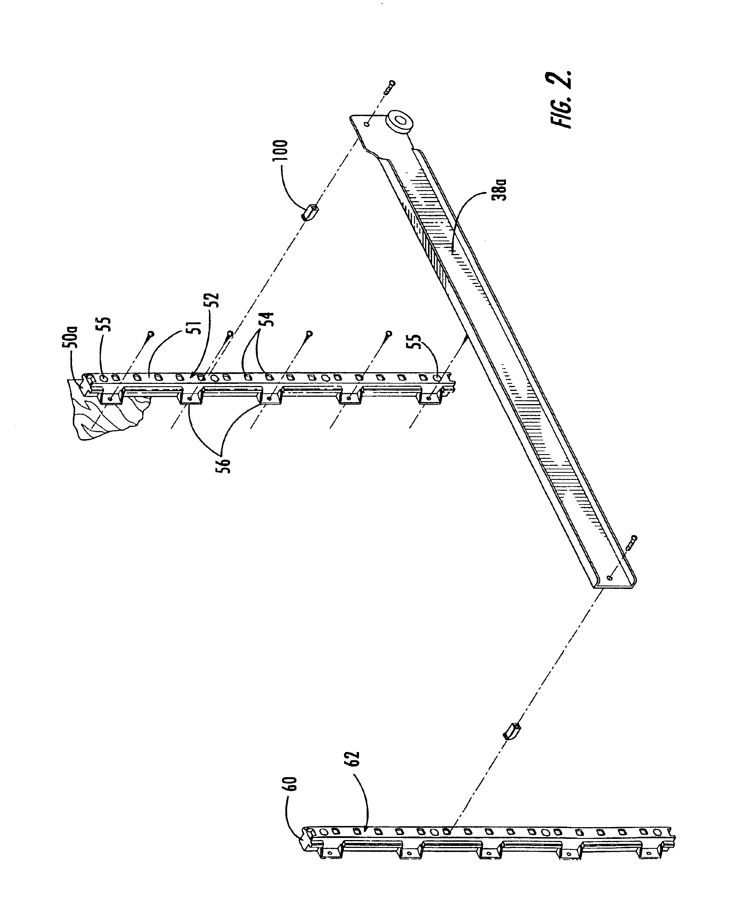
The present invention can provide a cabinet with drawers or trays that is easily assembled and can be retrofitted into many existing cabinets. As a first aspect, the present invention is directed to a cabinet adapted to receive a drawer that comprises: an enclosure comprising an upright rear wall and opposing upright side walls fixed at rear portions thereof to opposite ends of the rear wall; a pair of front elongate mounting members mounted generally upright in front portions of the side walls, each of the front mounting members having a mounting surface with a plurality of non-circular mounting apertures facing the other of the front mounting members; a pair of rear elongate mounting members mounted upright in rear portions of the side walls, each of the rear mounting members having a mounting surface with plurality of non-circular mounting apertures facing the other of the rear mounting members; a pair of slide members, each slide member extending between a respective rear mounting member and a respective front mounting member; and two pairs of mounting dowels, with one mounting dowel of each pair connecting a rear end portion of a slide member to a respective rear mounting member, and with the other mounting dowel of each pair connecting a front end portion of the slide member to a respective front mounting member. Each of the mounting dowels has a body that is non-circular in cross-section and that is sized and configured to be received in one of the plurality of apertures in a respective front or rear mounting member. The apertures for receiving the dowels are selected such that each slide member is generally horizontally disposed, and such that each slide member of the pair of slide members is mounted at approximately the same height as the other slide member of the pair. In this configuration, the height of a drawer or tray can be easily adjusted. Also, the configuration of the mounting system of the drawer or tray can be easily assembled in a new cabinet or retrofitted into an existing cabinet, whether that cabinet has one or multiple access openings.
In either of these embodiments, the front and rear mounting members are preferably of substantially identical configuration, as this can reduce manufacturing and shipping costs as well as facilitate assembly. It is also preferred that the front and rear mounting members have cutaway areas that can enable them to be mounted flush in the front and rear corners of the enclosure without interference from glue, staples or the like that may be present in the corners from assembly.
In an additional embodiment, the present invention is directed to a mounting dowel adapted to mount a drawer within a cabinet. Such a mounting dowel comprises: a body (preferably generally rectangular in cross-section) having a tapered portion at a first end thereof, the body having an aperture extending therewithin from a second end of the body opposite the first end; and a hook portion attached at the end of the body portion and extending generally perpendicular to a longitudinal axis of the body defined by the first and second ends. The body and hook portion are integrally formed as a unitary member. In this configuration, the dowel can be easily handled as it is attached to a slide member on which a drawer or tray is mounted, and can provide stability to the mounted drawer to prevent its sliding out of place during use. As a further embodiment, the present invention is directed to an assembly comprising a slide member for a sliding tray and a mounting dowel. The mounting dowel is of non-circular (preferably generally rectangular) cross-section. Any of the mounting dowel embodiments may include raised ridges or other texture on the surface thereof that is adapted to abut the slide member of a drawer assembly.
The present invention is further directed to a mounting member for a cabinet tray or drawer. The mounting member comprises: an elongate body portion having a front mounting surface and a longitudinal axis; and a plurality of non-circular apertures located in the front mounting surface. The body portion is a unitary structure and is formed of a polymeric material. As noted above, such a mounting member can provide significant performance advantages, and it also has the capacity for use in all areas of the cabinet, which can eliminate the need for separate “right-hand” and “left-hand” pieces as well as for “front” and “back” pieces. In another embodiment, the mounting member may be formed of any material and include at least one side wall connected to the mounting surface and a spacing ear extending from one of the side walls. In an additional embodiment, the body portion of the mounting member may be generally U-shaped and include a plurality of ribs extending from the front mounting surface and lining at least some of the apertures.
As a fourth aspect, the present invention is directed to a screw for fastening two members together, one of the members having a threaded receiving aperture, comprising: a head including recess adapted to receive a driving tool; and a threaded shank, wherein a portion of the shank is coated with a friction-imparting coating that increases friction between the shank and the threaded receiving aperture of the member. The presence of the friction-imparting coating can increase the tendency of the shank to remain stationary relative to the threaded receiving aperture.

Problems solved by technology

One issue with this system is the attachment of the round dowel to the slide member.
Because the dowel is typically relatively small (about 0.320 inch in diameter) and is round, it can be somewhat difficult to attach via screws to the slide member, as the dowel tends to spin undesirably during attachment.
Also, the round dowels tend to slide out of the holes in the vertical mounting member during shipping and / or use of the cabinet.
Moreover, the screws tend to “back-out” of the holes in the dowels, which can loosen the dowels or even cause them to become disconnected from the slide members.
However, in many instances glue and / or staples used to attach the front wall frame to the side walls are present in the corners.
Consequently, it may be difficult in some instances to position the mounting member flush against the corner.
Also, the relatively short length of the mounting members ordinarily requires the installer to position the mounting members precisely so that the holes of facing mounting members are at substantially the same height; otherwise, the tray or drawer may not be level when mounted.

Method used


Image

  • Rollout tray mounting system for cabinet
  • Rollout tray mounting system for cabinet
  • Rollout tray mounting system for cabinet

Examples


Embodiment Construction

The present invention will now be described more fully hereinafter, in which preferred embodiments of the invention are shown. This invention may, however, be embodied in different forms and should not be construed as limited to the embodiments set forth herein. Rather, these embodiments are provided so that this disclosure will be thorough and complete, and will fully convey the scope of the invention to those skilled in the art. In the drawings, like numbers refer to like elements throughout. Thicknesses and dimensions of some components may be exaggerated for clarity.

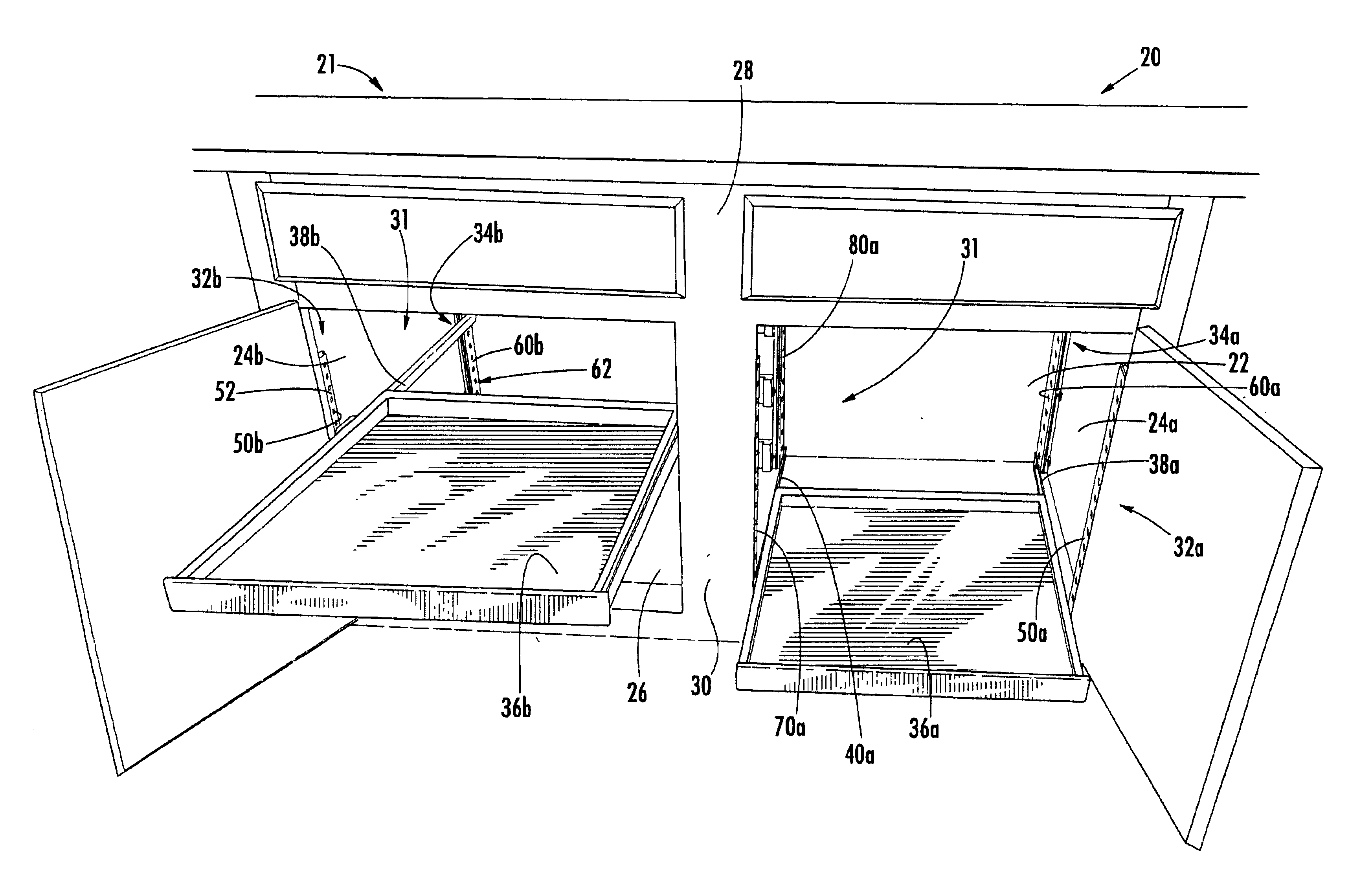
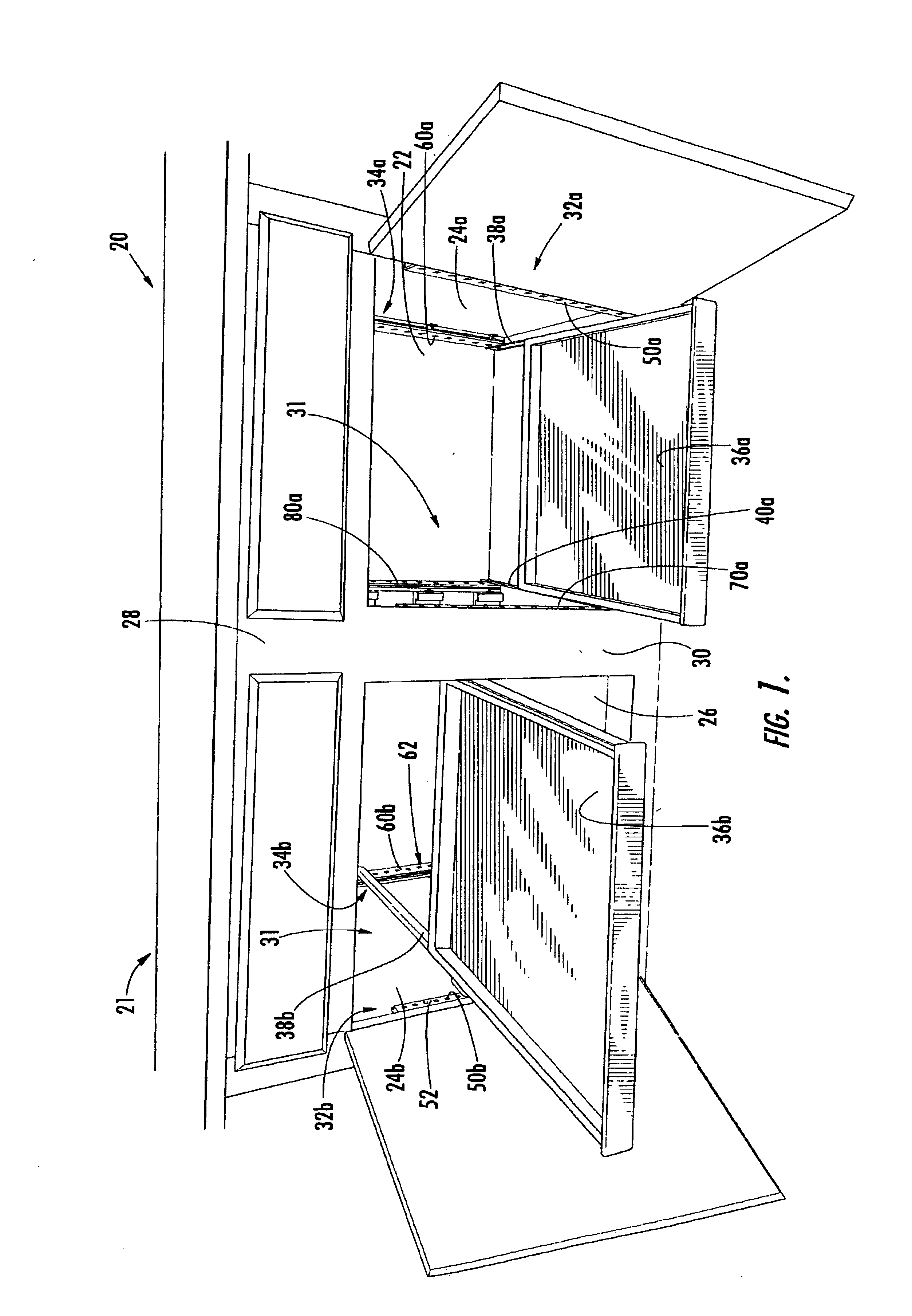
Referring now to the figures, a face-frame cabinet, designated broadly at 20, is illustrated in FIG. 1. The cabinet 20 includes an enclosure 21 having a rear wall 22, side walls 24a, 24b mounted perpendicular thereto, a floor 26 generally that is horizontally disposed, and a front wall 28 mounted generally parallel to the rear wall 22. The front wall 28 includes a vertical center member 30 that defines two access ope...


PUM


Abstract

A mounting member for a cabinet tray or drawer includes: an elongate body portion having a front mounting surface and a longitudinal axis; and a plurality of substantially rectangular apertures located in the front mounting surface. The body portion is a unitary structure and being formed of a polymeric material. This mounting member can be employed in cabinets to mount trays or drawers.

Description

FIELD OF THE INVENTIONThe present invention is directed generally to furniture, and more particularly to cabinets with sliding drawers and trays.BACKGROUND OF THE INVENTIONMany cabinets, particularly those found in kitchens, include drawers for storing various items. Often, drawers are mounted to the cabinet with elongate slide members that are fixed to the side walls of the drawer. Each slide member slidably engages a second elongate slide member that is fixed to the walls of the cabinet (often one of the slide members includes a small wheel that facilitates sliding motion). Some of such cabinets include multiple drawers, which can be disposed in vertically stacked fashion, side-by-side fashion, or both. When drawers are located side-by-side, typically slide members are mounted to the rear wall of the cabinet and to an upright member at the front of the cabinet that the slide members of the cabinet can engage.In some instances, it is desirable that the mounting height of the drawer...

Claims


Application Information

Patent Timeline
IPC IPC(8): A47B67/04A47B88/04A47B67/00
CPCA47B88/044A47B67/04A47B88/43
Inventor HIGHTOWER, ROBERT C.
Owner TENN TEX PLASTICS
Features
  • Generate Ideas
  • Intellectual Property
  • Life Sciences
  • Materials
  • Tech Scout
  • Unparalleled Data Quality
  • Higher Quality Content
  • 60% Fewer Hallucinations
Learn More