
Reflective projection display system

a projection display system and display screen technology, applied in the field of reflection projection display system, can solve the problems of enlarge the overall thickness, difficult to effectively reduce the overall -angle design, so as to achieve the effect of reducing the overall volume and thickness enhancing the contrast and reducing the back focus of the projection display system

Active Publication Date: 2005-01-11
DELTA ELECTRONICS INC
View PDF7 Cites 32 Cited by
  • Summary
  • Abstract
  • Description
  • Claims
  • Application Information

AI Technical Summary

Benefits of technology

An object of the invention is to provide a reflective projection display system with high contrast.
The invention has the following advantages. First, the back focus of the projection display system is reduced. Second, the deviation light ray and stray light ray in the dark-state mode are free from entering the projection lens, and the contrast of the projection display system is enhanced accordingly. Third, the overall volume and thickness of the projection display system is effectively reduced.

Problems solved by technology

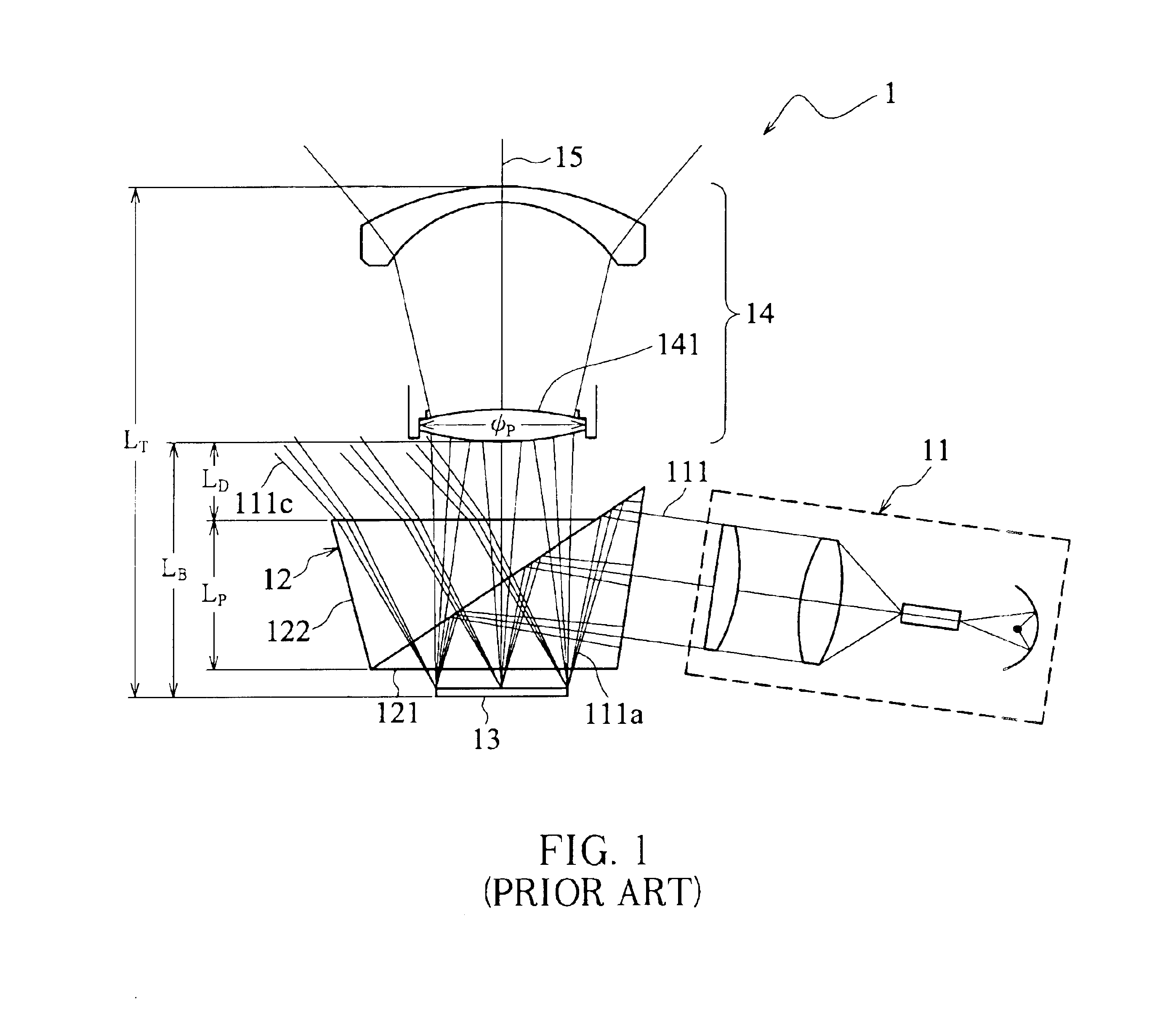
Consequently, such a method can increase the back focal distance LB and thus enlarge the overall thickness LT of the projection display system 1; therefore, there are difficulties in a wide-angle design, which preferably needs shorter back focal distance, of the projection lens 141.
Therefore, it is difficult to effectively reduce the overall thickness of the projection display system 1.

Method used


Image

  • Reflective projection display system
  • Reflective projection display system
  • Reflective projection display system

Examples


Embodiment Construction

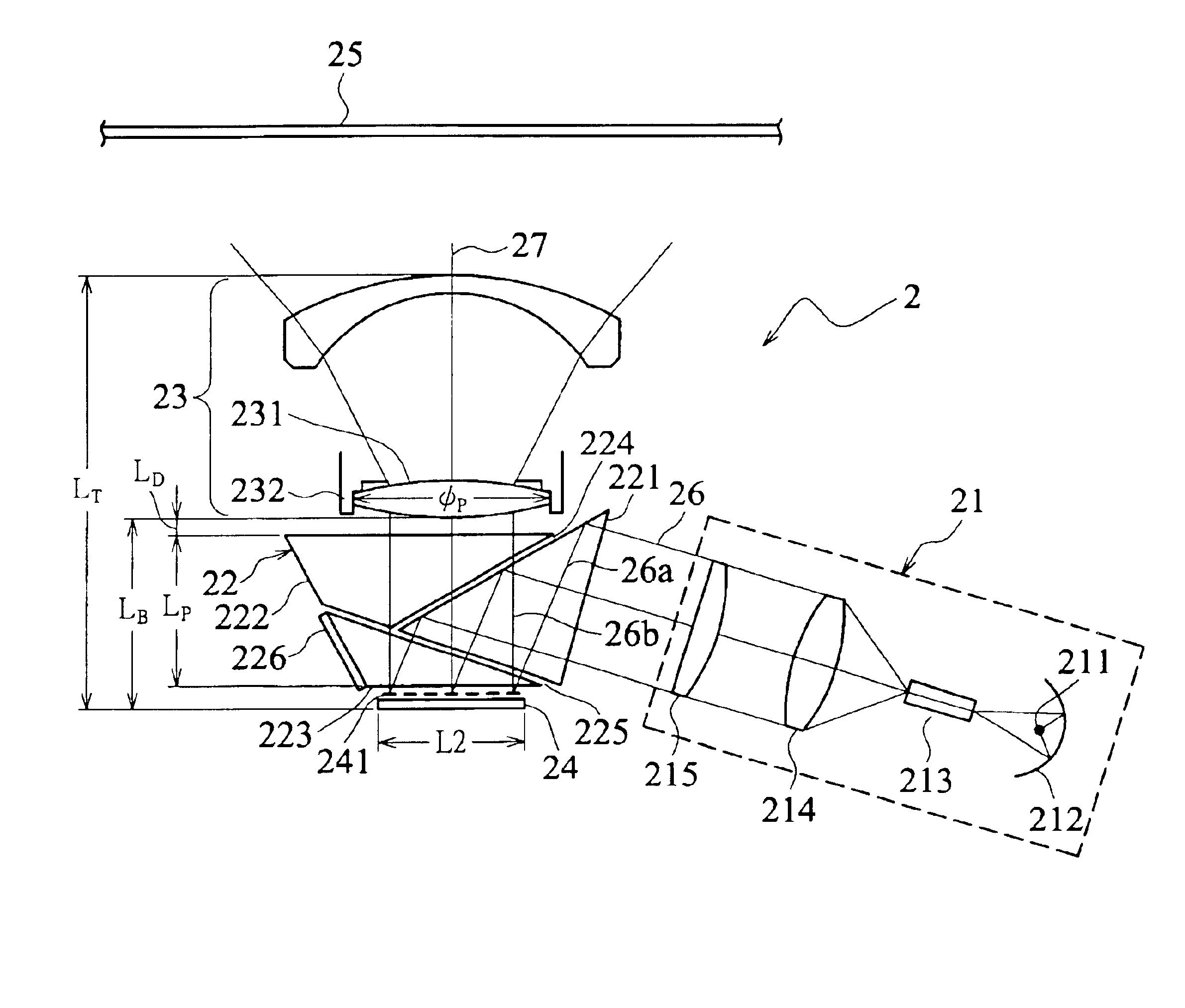
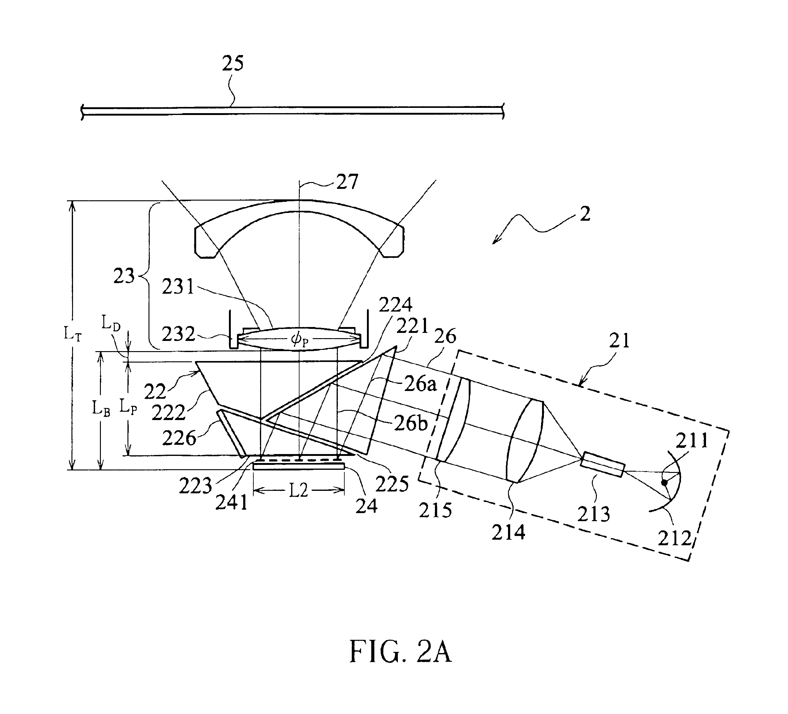
Referring to FIGS. 2A and 2B, a reflective projection display system 2 according to a first embodiment of the invention includes an illumination device 21, a prism set 22, a projecting device 23, and a reflective micro-mirror panel 24. The prism set 22 is arranged among the illumination device 21, the projecting device 23 and the reflective micro-mirror panel 24. The reflective projection display system 2 according to the first embodiment will be described in detail as follows.

The illumination device 21 includes a light source 211, a lamp shade 212, a light guide 213, a relay lens 214 and a collecting lens 215. The light source 211, the lamp shade 212 and the light guide 213 is so arranged that the light rays output from the light source 211 enters the light guide 213, passes through the relay lens 214 and the collecting lens 215, and then enters the prism set 22.

The prism set 22 includes three total internal reflection (TIR) prisms 221, 222 and 223 with an air gap 224 existing betw...


PUM


Abstract

A reflective projection display system for receiving a light ray and projecting it onto a screen in a light-state mode. The reflective projection display system includes a reflective micro-mirror panel, a projecting device and a prism set. Before reaching the reflective micro-mirror panel, the light ray is firstly reflected by the prism set. The light ray reflected by the reflective micro-mirror panel in the light-state mode directly passes through the prism set and is then received by the projection lens. The light ray reflected by the reflective micro-mirror panel in the dark-state mode is totally reflected at an interface between a prism adjacent to the reflective micro-mirror panel and an air gap adjacent to the prism.

Description

BACKGROUND OF THE INVENTION1. Field of the InventionThe invention relates to a reflective projection display system and, more particularly, to a projection display system using reflective micro-mirrors.2. Description of the Related ArtRecently, a technology of using reflective micro-mirrors to project images on large-scale monitors such as back projection televisions draws more and more attention and develops actively. The technology originated in the digital light processing technology, the imaging principle of which will be described in the following, developed by the Texas Instruments in 1987.As shown in FIG. 1, the uniformly incident light rays 111 outputted from an illumination device 11 to enter a prism set 12 composed of two prisms 121 and 122 are reflected by the prism set 12 and then projected onto a DMD (Digital Micro-mirror Device) 13 composed of ten thousands of micro-mirrors (not shown). Each micro-mirror on the DMD 13 has its individual driving electrode and steering s...

Claims


Application Information

Patent Timeline
Patent Type & Authority Patents(United States)
IPC IPC(8): G02B5/04H04N5/74G03B21/00G02B26/08
CPCH04N5/7458G02B5/04
Inventor CHANG, SEAN
Owner DELTA ELECTRONICS INC
Learn More