Apparatus for transporting and stacking goods, in particular in the form of plates, and corresponding process

Inactive Publication Date: 2005-01-11
KBA METALPRINT
View PDF10 Cites 19 Cited by
  • Summary
  • Abstract
  • Description
  • Claims
  • Application Information

AI Technical Summary

Benefits of technology

In so doing the feed velocity of the goods achievable by means of the feed transport device is preferably adjustable and constant. A process of this type permits a particularly gentle stacking of goods, such as, for example, of thin metal plates, and at the same time, in given cases, the setting of relatively high transport velocities since by means of the holding system the current goods are braked to a velocity of zero and thus in contradistinction to traditional processes no stopping of the current goods on absorption element has to be done, which could lead to undesired damage to the goods, such as, for example, a front edge of a plate. Furthermore, it is not necessary to provided a stacking fan to influence the “free flight path” of the current goods as is necessary in the case of conventional stacking processes.
According to a preferred embodiment variant the activation of the holding system occurs after reaching a transport surface of the overhead transport device in the holding area by means of the front area of the goods and, in particular, after producing a surface contact of the front area with the tr

Problems solved by technology

Dipping of this type, in particular in the case of metal plates with so-called “scroll plate sections,” is so pronounced that the relatively unstable corners swing through very sharply downwards.
Such undesired swinging motions of a current metal plate can lead to the front plate corner of a metal plate reaching the stacking device dipping into the section gap of a metal plate already lying (stored) in the stacking device and interlocking with its edges.
This leads to a disturbance of the stack in the device, said disturbance to be avoided as a matter of principle and frequently causing a complete running into one another of the metal plates and thus possibly leading to the entire production line coming to a stan

Method used


Image

  • Apparatus for transporting and stacking goods, in particular in the form of plates, and corresponding process
  • Apparatus for transporting and stacking goods, in particular in the form of plates, and corresponding process
  • Apparatus for transporting and stacking goods, in particular in the form of plates, and corresponding process

Examples


Embodiment Construction

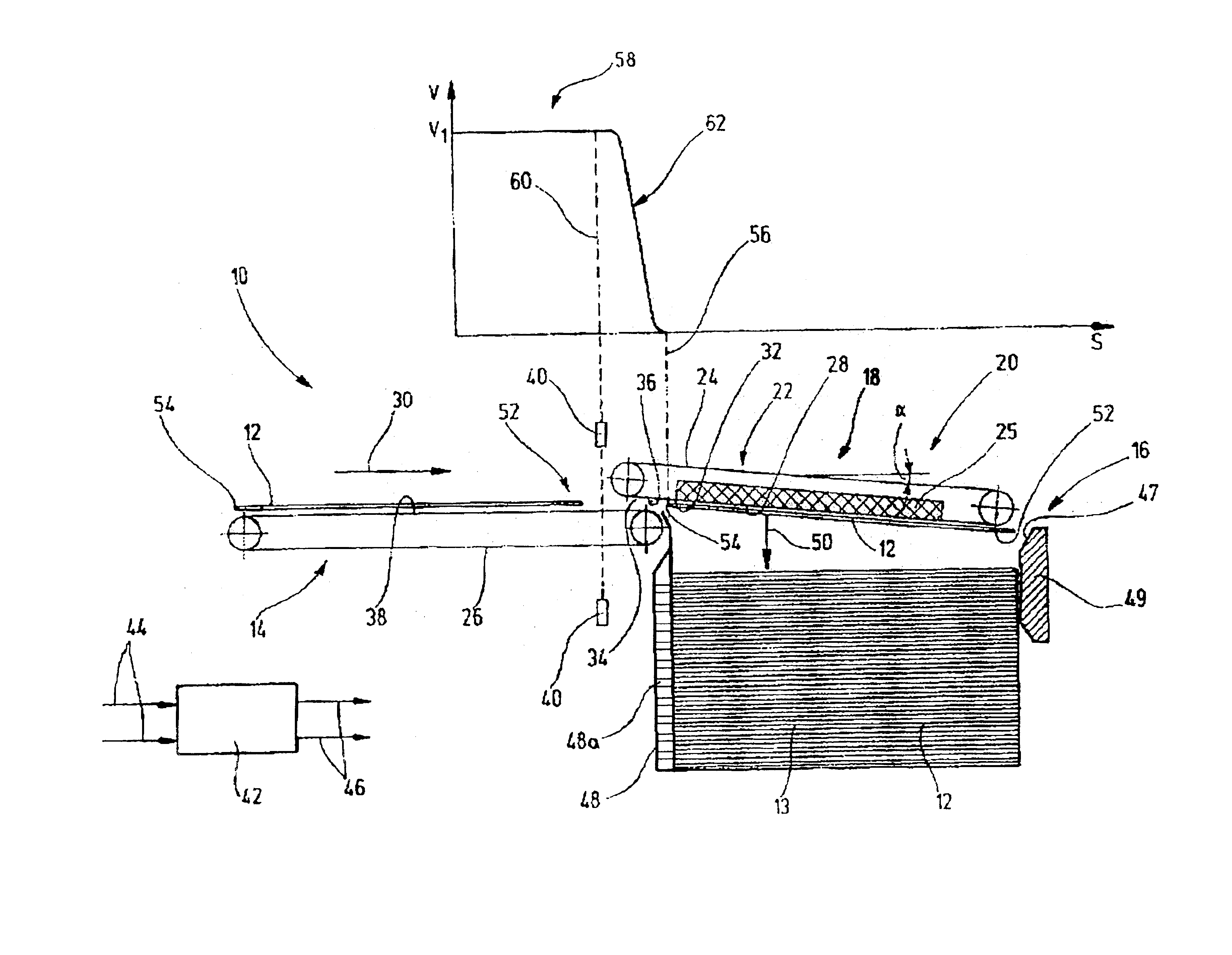
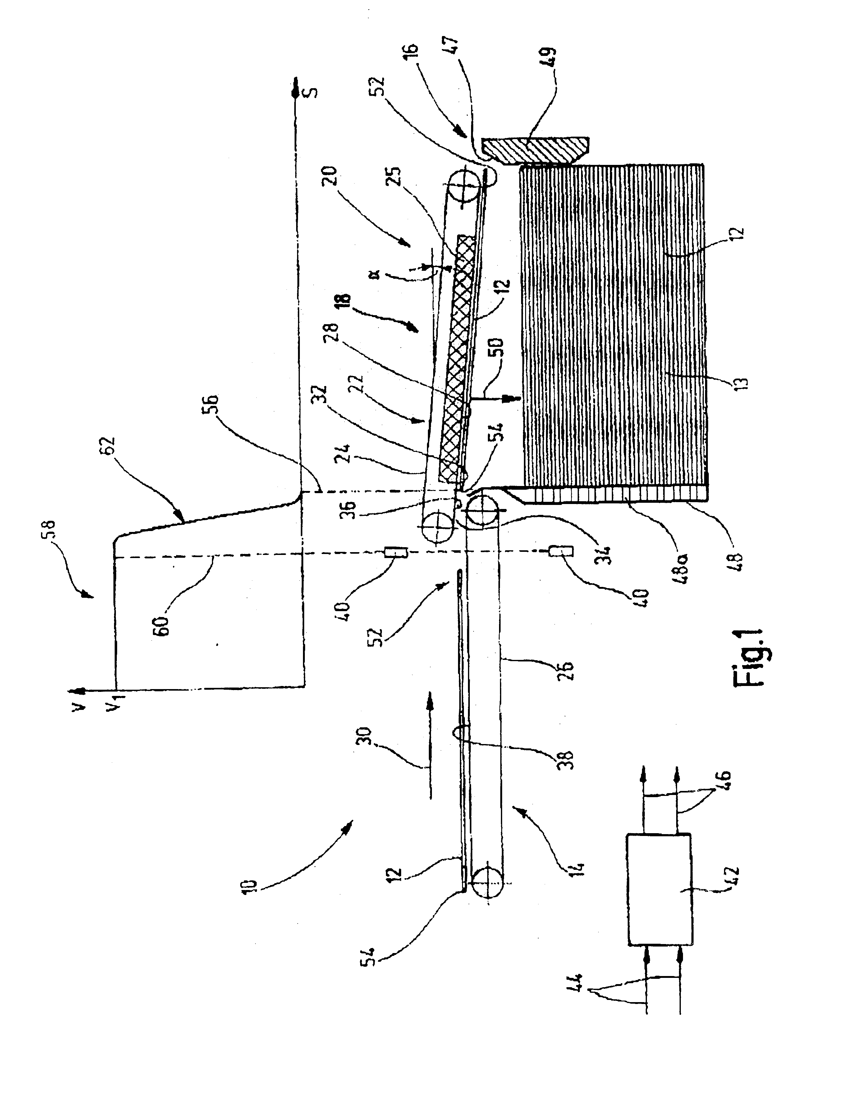
FIG. 1 shows a schematic representation of an apparatus generally designated as 10 for transporting and stacking of goods 12, in particular those in the form of a plate, such as, for example, metal plates or the like. Furthermore, in FIG. 1 a graph 58 of velocity as a function of transport path is represented in FIG. 1 (transport velocity V as a function of transport path S). The apparatus 10 contains a feed transport device 14 which has a transport surface 38 and is connected to a stacking device 16. In addition, an overhead transport device 18 is provided which is disposed above the stacking device 16 and extends completely along a stacking area 20. The overhead transport device 18 has an activatable and deactivatable as well as velocity-selectable holding system 22 by means of which a current metal plate 12 can be fixed on the overhead transport device 18. The overhead transport device 18 serves for braking the current metal plate 12 essentially up to a standstill in a stacking m...


PUM

PropertyMeasurementUnit
Angleaaaaaaaaaa
Angleaaaaaaaaaa
Lengthaaaaaaaaaa

Abstract

The apparatus (10) serves for transporting and stacking goods (12), in particular in the form of plates such as metal plates or the like, and includes a feed transport device (14), which is connected to a stacking device (16). In this apparatus an overhead transport device (18) is provided which is disposed at least partially in a stacking area (20) above the stacking device (16) and which has a holding system (22) which can be activated and deactivated, where a delay system is provided for time-delayed activation of an effective holding force of the overhead transport device at a point in time when the front, seen in the direction of transport, area of the goods overlaps the stacking area in the direction of stacking.

Description

BACKGROUNDThe invention relates to an apparatus for transporting and stacking of goods, in particular in the form of plates such as metal plates or the like, with a feed transport device which is connected to a stacking device according to the preamble of claim 1.Furthermore, the invention relates to a process for transporting and stacking goods, in particular in the form of plates such as metal plates or the like, where the current goods are fed by means of a feed transport device with an, in particular, adjustable feed rate, according to the preamble of claim [sic]15.Apparatuses and processes of the type stated initially are already known. In the case of traditional systems of this type, metal plates, in particular imprinted and / or lacquered, running in tandem are introduced into a stacking device, by way of example formed as a stack box, and there are stacked lying on one another. Therein the metal plate feed is accomplished by means of a feed transport device connected at the fr...

Claims


Application Information

Patent Timeline
IPC IPC(8): B65H29/26B65G57/04B65G57/02B65H29/32B65H29/30B65H31/36
CPCB65G57/04B65H29/26B65H2301/44336B65H2301/44332B65H2301/44322B65H29/30B65H29/32
Inventor BJORN, MICHELSTEPHAN, GERICKE
Owner KBA METALPRINT
Why Eureka
Try Eureka