Multi cyclone vacuum cleaner

a vacuum cleaner and multi-cyclone technology, applied in the field of vacuum cleaners, can solve problems such as inconvenience for users, and achieve the effects of enhancing the reliability of the user's emptying of the dust collector, maximizing the dust capacity, and easy discarding

Inactive Publication Date: 2005-01-11
LG ELECTRONICS INC
View PDF2 Cites 110 Cited by
  • Summary
  • Abstract
  • Description
  • Claims
  • Application Information

AI Technical Summary

Benefits of technology

An advantage of the present invention is to provide a canister type vacuum cleaner using a dual type cyclone dust collector having a primary cyclone dust collector with a maximized dust capacity.
is to provide a canister type vacuum cleaner using a dual type cyclone dust collector having a primary cyclone dust collector with a maximized dust capacity.
It is another advantage of the present invention to provide a vacuum cleaner in which the user may easily discard foreign matters collected in the dust collector, thereby enhancing the reliability of the user's emptying of the dust collector.
It is a further advantage of the present invention to provide a vacuum cleaner to perform iterative cleaning of the fine dust exiting the secondary cyclone dust collector.
To achieve the above advantages of the present invention, there is provided a multiple cyclone vacuum cleaner including: a cleaner body having mountings for a fan and a fan motor, and mounting for a primary cyclone body and dust tank; a first air inlet passage connected to the dust tank, for the intake of air and various foreign matter, a first air outlet passage at the top of the dust tank, for exhausting the air firstly removed of the foreign matter, a secondary cyclone body on the dust tank, for circulation of air in a direction perpendicular to the axial direction of the dust tank; a second air inlet passage connected to the first air outlet passage and the secondary cyclone body, for introducing the air and the foreign matters exhausted from the air outlet passage to the secondary cyclone body; a second air outlet passage exiting the lateral side of the secondary cyclone body near the second air inlet passage; and a foreign matter outlet passage connected to the secondary cyclone body and a second dust tank, for collecting the foreign matters separated from the air in the secondary cyclone body.
In another embodiment of the present invention, a vacuum cleaner has a removable cyclone dust collector in a cleaner body, wherein the cyclone dust collector sucks air containing foreign matter, separates the foreign matter from the air by cyclone action, collects the foreign matters in a dust tank, and exhausts the air to an air outlet passage connected to a fan, wherein the multiple cyclone vacuum cleaner includes a removable filter structure in the cleaner body connected to the air outlet passage of the cyclone dust collector having a dust filter for a second collection of fine dust contained in the air.

Problems solved by technology

In other words, the above-described dual cyclone dust collector has such a low dust capacity that it cannot be applied to a canister type vacuum cleaner thereby inconveniencing users.

Method used


Image

  • Multi cyclone vacuum cleaner
  • Multi cyclone vacuum cleaner
  • Multi cyclone vacuum cleaner

Examples


first embodiment

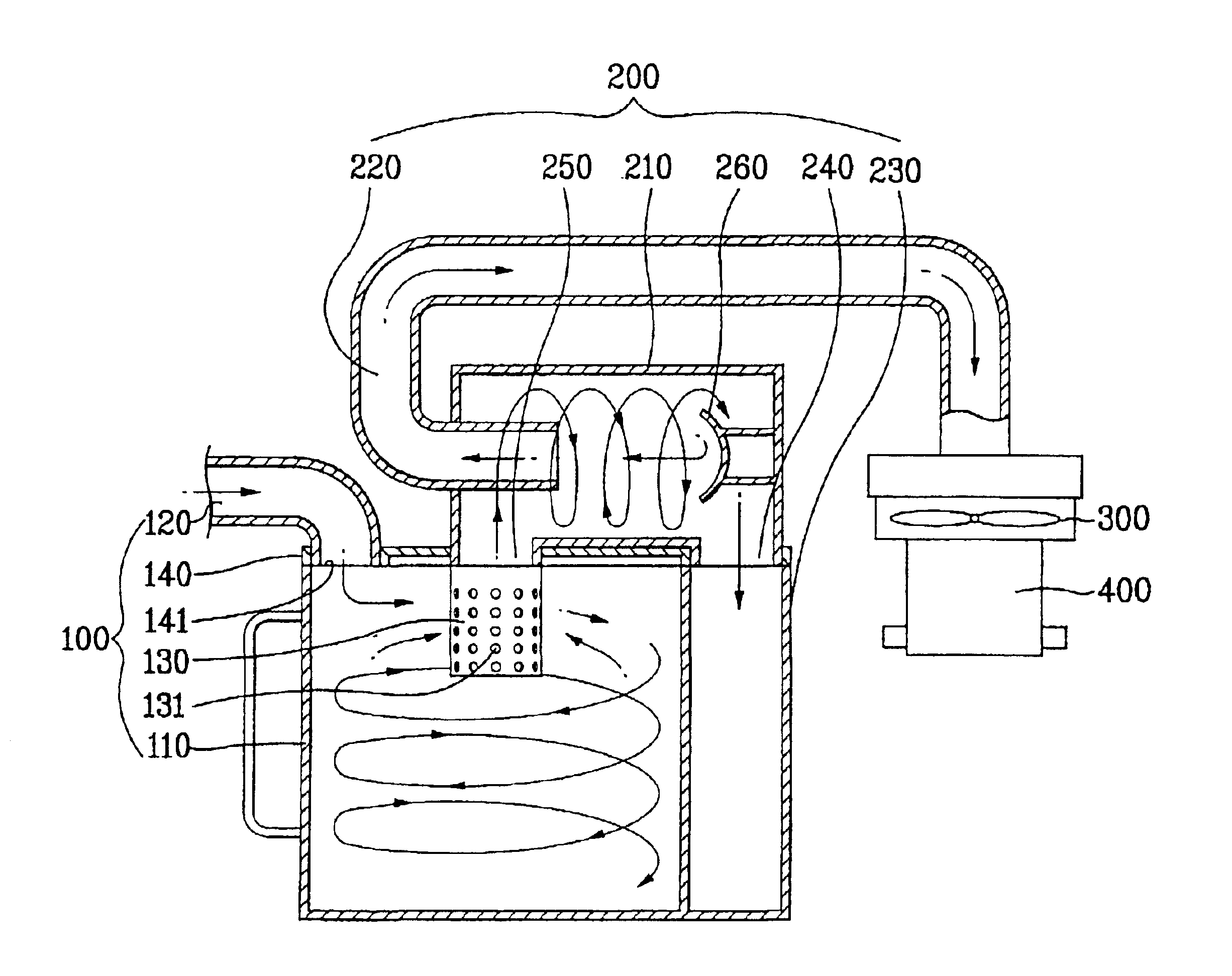
In an example where the multiple cyclone dust collector is used in the cleaner body 10 of the canister type vacuum cleaner according to the present invention as constructed above, the dust collector volume is maximized.

Next, a detailed description of the operation of the multiple cyclone vacuum cleaner according to the first embodiment of the present invention as constructed above is given.

First, the fan motor 400 rotates the fan 300 to cause a suction force. Air and various foreign matters are sucked into a suction opening body 20 constituting the vacuum cleaner and introduced into the first air inlet passage 120 of the primary cyclone dust collector 100 via an extension pipe 30 and the suction hose 40. Thus, the foreign matter is successively introduced into the primary cyclone body and dust tank 110. Foreign matter relatively large with respect to the diameter of the through holes 131 of the first air outlet passage 130 are collected in the dust tank 110. The air and foreign matt...

second embodiment

FIGS. 7 to 10 illustrate a multiple cyclone vacuum cleaner according to the present invention.

In the second embodiment of the present invention, a filter structure 500 is further provided between the second air outlet passage 220 constituting the secondary cyclone dust collector 200 and the fan 300, and a dust filter 510 is provided in the filter structure 500 for collecting the fine dust left in the air. The filter structure 500 is detachable from the cleaner body 10 in order to easily perform cleaning. For this purpose, receptacle 150 for receiving the filter structure 500 is provided on a top anterior side of the intermediate body 12 of the cleaner body 10. The receptacle 150 is positioned on the topside of the intermediate body 12. The receptacle 150 is connected to the fan.

The above filter structure 500 completely eliminates various fine foreign matters not removed by the cyclone effect with a separate filter 500. The structure is configured to completely remove the lightest pa...


PUM

PropertyMeasurementUnit
circumferenceaaaaaaaaaa
tensionaaaaaaaaaa
transparentaaaaaaaaaa

Abstract

The disclosure is directed to a cyclone dust collector for separating air from dusts by way of a centrifugal force and, more particularly, to a novel canister type vacuum cleaner capable of using a dual cyclone dust collector with maximized allowable dust capacity. The entire structure of the vacuum cleaner as suggested herein is configured for the user's simple manipulation in discarding various foreign matters collected in the vacuum cleaner, thereby improving reliability to the user.

Description

BACKGROUND OF THE INVENTION1. Field of the InventionThe present invention relates generally to a cyclone dust collector making use of cyclone action and, more particularly, to a vacuum cleaner provided with the cyclone dust collector.2. Discussion of the Related ArtAmong the cyclone dust collectors, a duel type cyclone dust collector comprising a primary cyclone dust collector 1 and a secondary cyclone dust collector is configured to perform iterative collection of foreign matters more effectively than a single cyclone dust collector.FIGS. 1 to 3 illustrate an application of the above-stated dual type cyclone dust collector to an upright type vacuum cleaner. The upright vacuum cleaner has a dual type cyclone dust cleaner including primary and secondary cyclone dust collectors 1 and 2 provided in a cleaner body, a fan 3 provided at the bottom in the cleaner body for generating the suction force, and a fan motor 4 for driving the fan 3.The dual type cyclone dust collector operates by ...

Claims


Application Information

Patent Timeline
Patent Type & Authority Patents(United States)
IPC IPC(8): A47L9/16A47L9/10A47L9/12A47L9/32A47L9/00B01D45/12B04C5/187B04C5/26
CPCA47L9/00A47L9/122A47L9/1608A47L9/1625A47L9/327B01D45/12B04C5/187B04C5/26A47L9/1683Y10S55/03
Inventor KIM, DAE CHUL
Owner LG ELECTRONICS INC
Why Eureka
Try Eureka