High-power ion sputtering magnetron

a magnetron and high-power technology, applied in the direction of electrolysis components, vacuum evaporation coatings, coatings, etc., can solve the problems of high-power alternating current ion sputtering magnetrons, equipment failure, manufacturing plant line shutdowns caused by such failures, etc., to reduce shorting and arcing incidents, block electrical noise, and protect heat-sensitive parts

Inactive Publication Date: 2005-01-11
BUEHLER AG
View PDF11 Cites 42 Cited by
  • Summary
  • Abstract
  • Description
  • Claims
  • Application Information

AI Technical Summary

Benefits of technology

Still another advantage of the invention is that it shields heat-sensitive parts by absorbing fluctuating magnetic fields and blocks electrical noise.
is that it shields heat-sensitive parts by absorbing fluctuating magnetic fields and blocks electrical noise.
Yet another invention advantage is that the electrical brushes are placed inside the cathode cooling system where dust is flushed out and cannot bridge insulators inside the cathode thereby reducing incidents of shorting and arcing. Because these brushes are internal to the cathode, the brushes could be distributed evenly inside the target allowing a more uniform power distribution and therefore providing more uniform target wear and a more uniform coating and deposition on the product. However, the brushes could be disposed anywhere inside the cathode cooling system, such as inside the cathode drive shaft.
The rotary cathode device for an ion sputtering magnetron of the present invention comprises a conducting member disposed within the rotary cathode device. The conducting member is made of an electrically conductive material for conducting electrical current from the power supply to the rotary cathode device. The conducting member is preferably a coolant conduit.
The rotary cathode device further comprises a drive shaft portion which includes an interior surface and an exterior surface. The drive shaft portion is further made of an electromagnetic field-permeable material such as a ferrous material.
In other embodiments of the invention, the drive shaft need not be made of any particular material, but instead, an electromagnetic field shield is disposed between the conducting member and the drive shaft portion with the shield being made of an electromagnetic field-permeable material. For example, in another preferred embodiment of the invention, the electromagnetic field shield is attached to at least a portion of the interior surface of the drive shaft portion or the shield is made of electromagnetic field-permeable material.

Problems solved by technology

With these advances have come the important problems of equipment failure due to magnetic inductive heating of parts.
Manufacturing plant line shutdowns caused by such failure are extremely expensive because significant downtime and repair costs are required to fix damaged equipment.
Ion sputtering magnetrons utilizing high-power alternating current are susceptible to such damage and failure from magnetic inductive heating of its sensitive parts.
For example, a rotary cathode used in an ion sputtering magnetron is susceptible to seizure from a number of failure modes.
As alternating current and frequency increase, parts in the sputtering magnetron become more susceptible to heat damage.
Failure can also be due to rotary seal leakage caused by overheating.
Still another failure can be insulation breakdown due to exposure to overheated neighboring parts.
Consequently, another significant failure point is the rotary seal which is susceptible to being easily damaged from excessive inductive heating.
Additional failure modes with this rotary seal include seizure and atmospheric leakage which will shut down the sputtering process and, consequently, the manufacturing line, at great cost.
Another significant problem encountered is when the target material of a rotary cathode sputters mostly at one end of the target at the point where electricity from the drive shaft connects to the target.
This causes non-uniform coatings on the product that need to be compensated for by masking or other problematic or expensive means.
Shutting down the manufacturing line to replace those rotary cathode targets is also very costly.
Still another problem caused by high power is resistive heating.
Resistive heating of parts in the current path also limits the power that can be applied.
Yet another problem is shorting and arcing at higher powers and voltages due to conductive dust from the electrical brushes that bridges insulators inside existing cathode design.

Method used


Image

  • High-power ion sputtering magnetron
  • High-power ion sputtering magnetron
  • High-power ion sputtering magnetron

Examples


Embodiment Construction

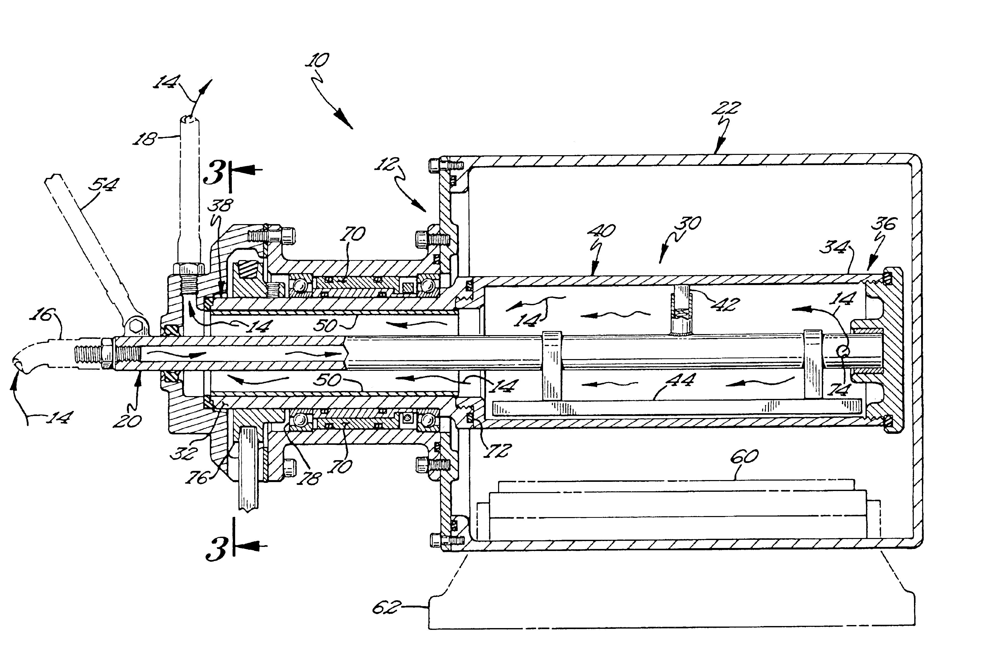
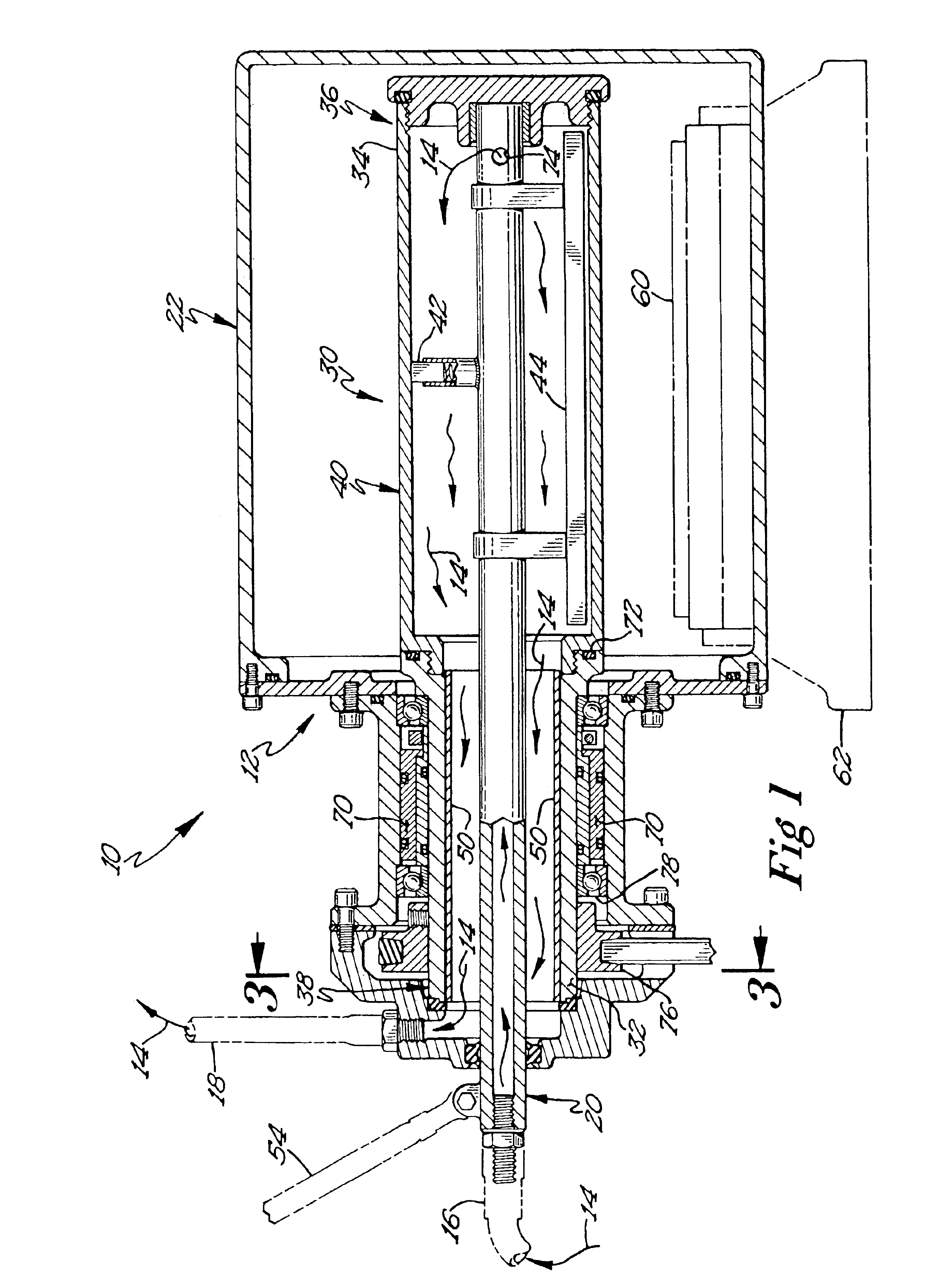
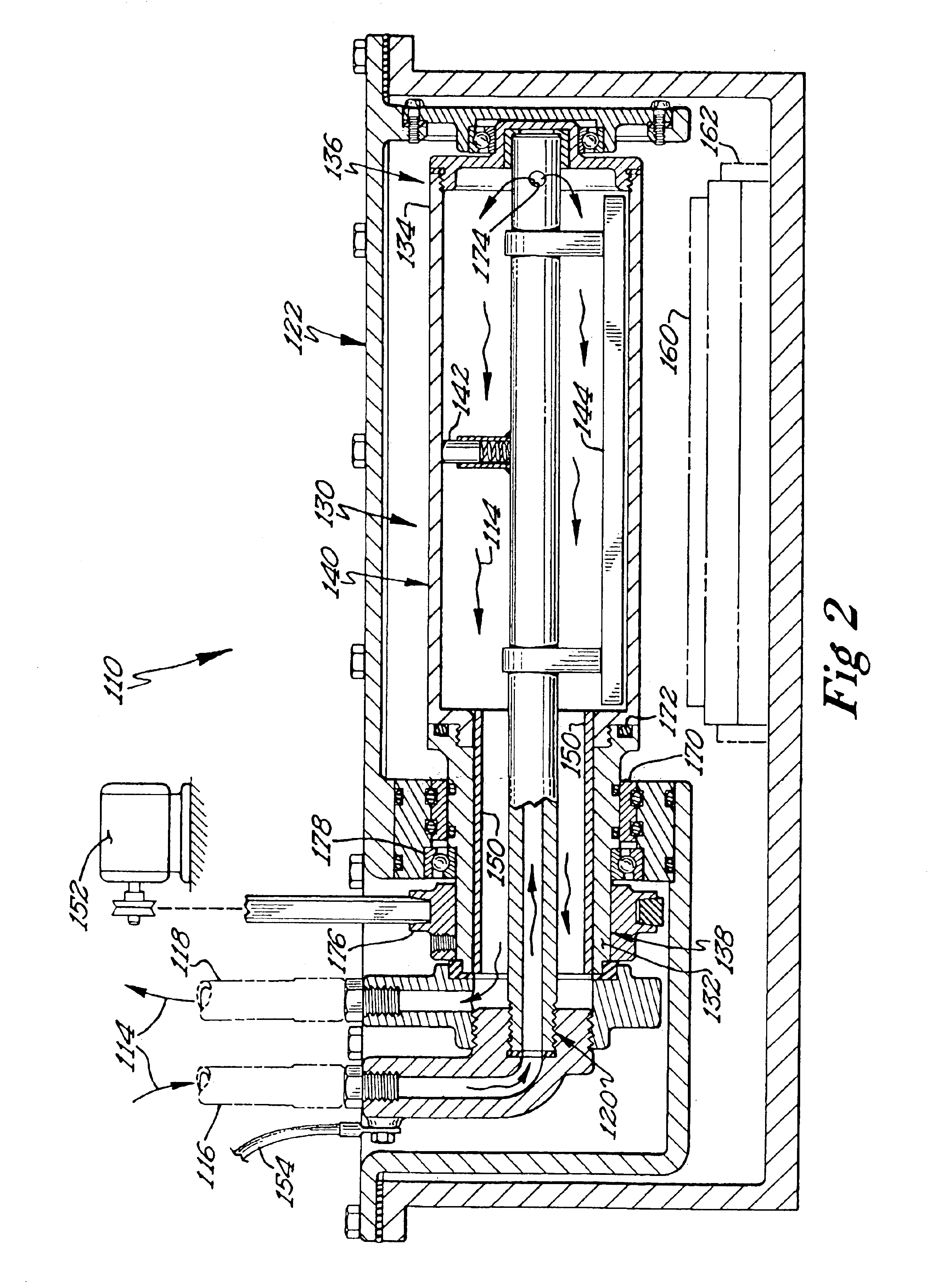
To assist in the understanding of the preferred embodiments illustrated in the FIGS. 1 through 5, it will be assumed that

Magnetic shielding materials entrap magnetic flux at various locations such as at the magnetic flux source or shield a sensitive component. The optimum shielding strategy and shield location typically involve performance, complexity of design, and cost considerations. A passive shielding strategy is a type of magnetic shielding strategy which relies on the interactions between magnetic fields and special high permeability materials.

The dynamic interactions between AC and DC magnetic fields and their role in a passive shielding strategy may involve six parameters: frequency, attenuation, saturation, magnetic field strength, magnetic flux density and material permeability.

The magnetic field strength, called the “H” field, describes the intensity of a magnetic field in free space at some distance away from its source. Field strength (H), measured in Oersteds (Oe), is...


PUM

PropertyMeasurementUnit
electrically conductiveaaaaaaaaaa
electromagnetic fieldaaaaaaaaaa
electromagnetic field-permeableaaaaaaaaaa

Abstract

A high-power ion sputtering magnetron having a rotary cathode comprising a conducting member disposed within the rotary cathode being made of an electrically conductive material for conducting electrical current from the power supply to the rotary cathode. The ion sputtering magnetron also has an electromagnetic field shield disposed between the conducting member and the drive shaft portion. The field shield is made of an electromagnetic field-permeable material such as a ferrous material for reducing damage to parts adjacent to the conducting member that are susceptible to inductive magnetic heating.

Description

BACKGROUND OF THE INVENTIONThis invention relates generally to thin film coating deposition devices. More particularly, the present invention relates to shielded rotary cathodes for use in high-powered ion sputtering magnetrons.Rotary or rotating cylindrical cathodes were developed to overcome some of the problems associated with planar magnetrons. Examples of the rotating cathode are further described in U.S. Pat. Nos. 4,356,073 and 4,422,916, the entire disclosures of which are hereby incorporated by reference. Various mounting, sealing and driving arrangements for cylindrical cathodes are described in U.S. Pat. Nos. 4,443,318; 4,445,997; 4,466,877, the entire disclosures of which are hereby incorporated by reference. Those patents describe rotating cathodes mounted horizontally in a coating chamber supported at both ends. It is often preferable to support the rotary cathode at only one end by a cantilever mount such as described in U.S. Pat. No. 5,200,049, the disclosure of which...

Claims


Application Information

Patent Timeline
Patent Type & Authority Patents(United States)
IPC IPC(8): H01J37/32H01J37/34C23C14/34
CPCH01J37/3405H01J37/3497H01J37/3411
Inventor CROWLEY, DANIEL T.
Owner BUEHLER AG
Why Eureka
Try Eureka