Electrochemical-sensor design

Inactive Publication Date: 2005-01-11
BAYER CORPORATION +1
View PDF1 Cites 273 Cited by
  • Summary
  • Abstract
  • Description
  • Claims
  • Application Information

AI Technical Summary

Problems solved by technology

The counter electrode contains a sub-element which is located upstream of the working electrode, so that when electrical communication between only the sub-element of the counter electrode and working electrode due to incomp

Method used


Image

  • Electrochemical-sensor design
  • Electrochemical-sensor design
  • Electrochemical-sensor design

Examples


example i

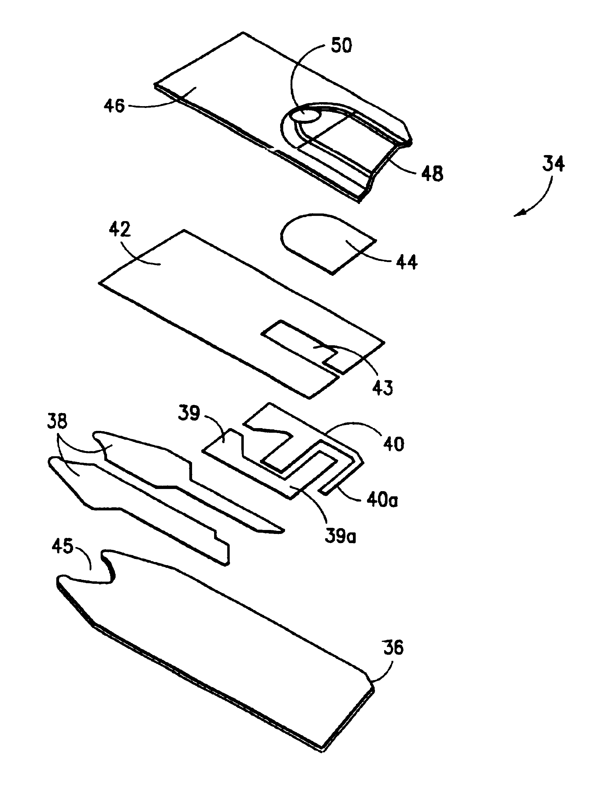
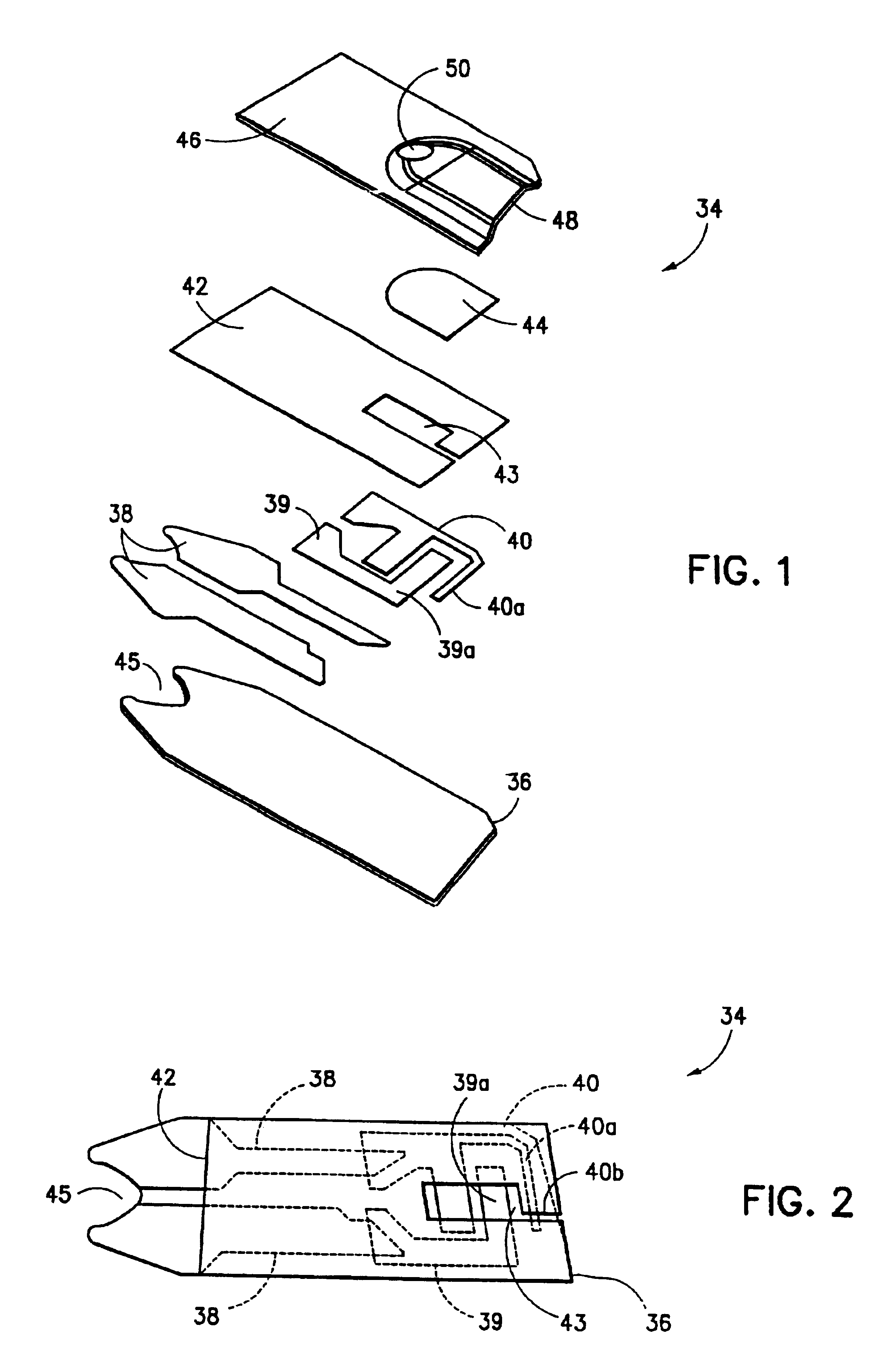
The base stock, typically of polycarbonate, is printed with various inks to form the electrodes 39 and 40 and then overcoated with a dielectric layer 42 in a predetermined pattern designed to leave a desired surface of the electrode exposed to contact by the fluid test sample as it enters the space formed by the mating of lid 46 and base 36. The particular configuration of the dielectric layer 42 as depicted in FIG. 1 in which opening 43 leaves the reagent layer in electrical communication with the electrodes 39 and 40 is designed to define the extent to which all of the conductive elements (working, reference and sub-element electrodes) are exposed to the test fluid. Along with the printed conductive features, the dielectric layer defines the size of each of these elements. The electrodes are preferably printed so that the conductive and dielectric layers are close to 90 degrees to each other. This helps in the tolerance stackup for building the sensor because it reduces the regist...


PUM

PropertyMeasurementUnit
Electric potential / voltageaaaaaaaaaa
Timeaaaaaaaaaa
Timeaaaaaaaaaa

Abstract

An improved electrochemical sensor having a base bearing a working and counter electrode which provides a flow path for a fluid test sample. The working and counter electrodes are configured so that a major portion of the counter electrode is located downstream on the flow path from the working electrode with the exception of a small sub-element of the counter electrode which is in electrical communication with the primary portion of the counter electrode and located upstream of the working electrode. This configuration enables the sensor when the capillary space is incompletely filled with test fluid.

Description

BACKGROUND OF THE INVENTIONThe present invention relates to an electrochemical biosensor that can be used for the quantitation of a specific component (analyte) in a liquid sample. Electrochemical biosensors of the type under consideration are disclosed in U.S. Pat. Nos. 5,120,420 and 5,264,103. These devices have an insulating base upon which carbon electrodes are printed with the electrodes being covered with a reagent layer comprising a hydrophilic polymer in combination with an oxidoreductase specific for the analyte. These patents typically involve a spacer element, a generally U shaped piece and a cover piece, so that when the base, spacer element and cover piece are laminated together, there is created a capillary space containing the electrodes covered by the reagent layer. In addition to the oxidoreductase, there is included an electron acceptor on the reagent layer or in another layer within the capillary space. A hydrophilic polymer, e.g. carboxymethylcellulose, is used t...

Claims


Application Information

Patent Timeline
IPC IPC(8): C12Q1/00G01N33/487
CPCG01N27/3274C12Q1/001
Inventor MUSHO, MATTHEW K.NOELL, J. OAKEYEDELBROCK, ANDREW J.HUANG, DIJIA
Owner BAYER CORPORATION
Why Eureka
Try Eureka