Vehicle-use alternator enabling accurate control of position and attitude of the alternator during an operation of mounting the alternator in a vehicle

a technology of vehicle-use alternators and position and attitude control, which is applied in the direction of supporting/enclosing/casings, dynamo-electric components, and magnetic circuit shapes/forms/constructions, etc. it can solve the problems of affecting the movement affecting the required position of the engine, so as to avoid the effect of excessive increase in the manufacturing cost of the suspended alternator due to the incorporation o

Inactive Publication Date: 2005-01-11
DENSO CORP
View PDF11 Cites 2 Cited by
  • Summary
  • Abstract
  • Description
  • Claims
  • Application Information

AI Technical Summary

Benefits of technology

It is an objective of the present invention to overcome the above problems of the prior art, by providing a vehicle-use alternator whereby obstruction of movement of the alternator during an operation for mounting the alternator can be avoided, and whereby the alternator can be accurately maintained in a required attitude during the mounting operation.
To achieve the above objectives, the invention provides a vehicle-use alternator (referred to in the following simply as an alternator) having a housing that contains a rotor and stator and is formed with attachment holes for use during an operation of mounting the alternator in a vehicle, wherein the housing is formed with a plurality of carrier portions, each having at least one through-hole or groove formed therein, for use in supporting the alternator during the mounting operation. As a result, the alternator can be held supported on a rod-shaped carrier jig that is passed through the holes or within and below the grooves, during the mounting operation. The alternator can thereby be held in a desired attitude throughout the process of moving the alternator into the required position, and subsequent attachment of the alternator.
With such an alternator, preferably each of the through-holes or grooves constituting the carrier portions are oriented along a common axis. In that way, a carrier member which is of straight elongated form can be passed through each of the plurality of holes or grooves constituting the carrier portions, and the alternator can thereby be retained and supported on the carrier member. The alternator can thereby be moved towards a position at which it is to be attached, without that movement being obstructed by any equipment that is located above that attachment position, such as the engine head.
Furthermore with such an alternator, each of the holes or grooves constituting the carrier portions preferably has a central axis oriented in a direction that is other than parallel to an axis of rotation of the rotor of the alternator. In that way it becomes possible to maintain the alternator in an arbitrarily determined attitude while it is being moved towards an attachment position, while avoiding obstruction of that movement by other nearby equipment.
Moreover such an alternator can be configured with the aforementioned attachment holes having respective central axes in parallel with one another, and with each of the through-holes or grooves formed in the carrier portions having a central axis oriented in a direction that is other than parallel to the central axes of the attachment holes. In that way, the alternator can be moved towards the position at which it is to be mounted, by motion along a direction that is not parallel to the axes of the attachment holes. In addition, the outer faces of the attachment holes can be held oriented at a required angle of tilt while the alternator is being moved towards its mounting position, so that for example the alternator can readily be attached to a sloping side of an engine block.
The carrier portions can be advantageously formed in one or more attachment stays of the alternator, i.e., with the attachment stays having respective ones of the attachment holes formed therein. In that way, it becomes unnecessary to alter an existing shape of a housing of the alternator, for the purpose of providing external protrusions, etc., through which the holes constituting the carrier portions would be formed, since these holes can be formed in pre-existing parts of the alternator that are necessarily incorporated to enable attachment of the alternator by means of bolts, etc. Thus, excessive increase in manufacturing cost of the alternator due to incorporation of the carrier portions can be avoided.

Problems solved by technology

However when such a side-mounted alternator is being lowered towards such a required position, in a suspended condition, the problem arises that movement of the suspended alternator may be obstructed by the engine head, or by some other equipment that is located near the engine, e.g., when the engine head or some other piece of equipment protrudes above the location where the alternator is to be mounted (that is to say, extends above the outer ends of the attachment holes that are formed in the engine bracket).
Similarly, horizontal movement of the suspended alternator, towards the required position for attachment to the engine bracket, may also be similarly obstructed.
It may thereby become difficult or impossible to accurately align the attachment holes formed in the alternator with the attachment holes in the engine bracket.
Moreover, if the alternator is simply held suspended by chains, etc., when performing this positioning operation, it becomes difficult to maintain the alternator in a desired attitude, so that the alternator can be attached with a required angular orientation.

Method used


Image

  • Vehicle-use alternator enabling accurate control of position and attitude of the alternator during an operation of mounting the alternator in a vehicle
  • Vehicle-use alternator enabling accurate control of position and attitude of the alternator during an operation of mounting the alternator in a vehicle
  • Vehicle-use alternator enabling accurate control of position and attitude of the alternator during an operation of mounting the alternator in a vehicle

Examples


Embodiment Construction

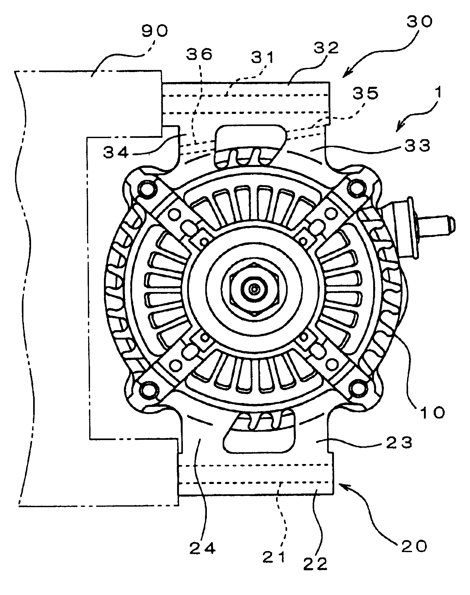
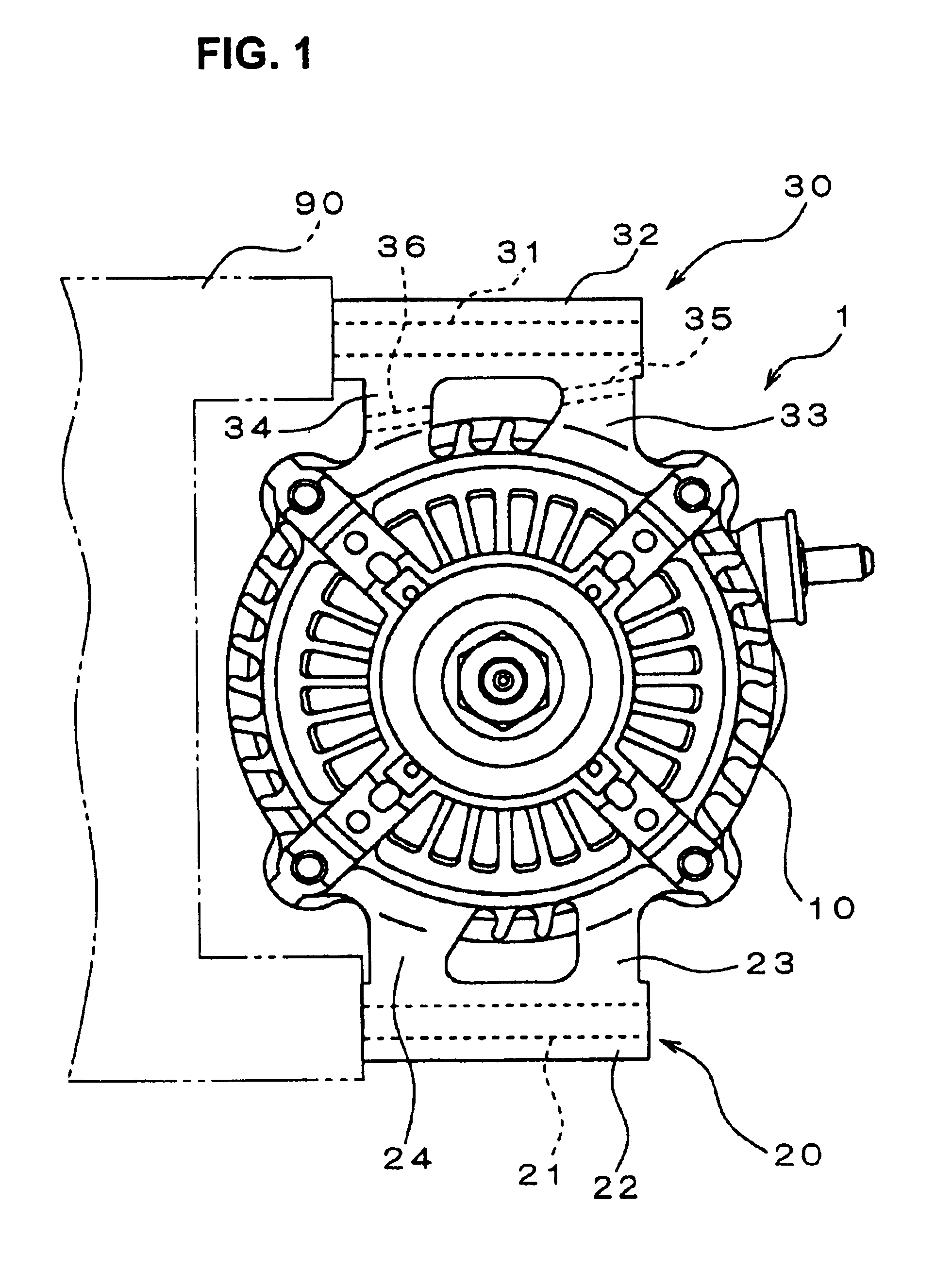
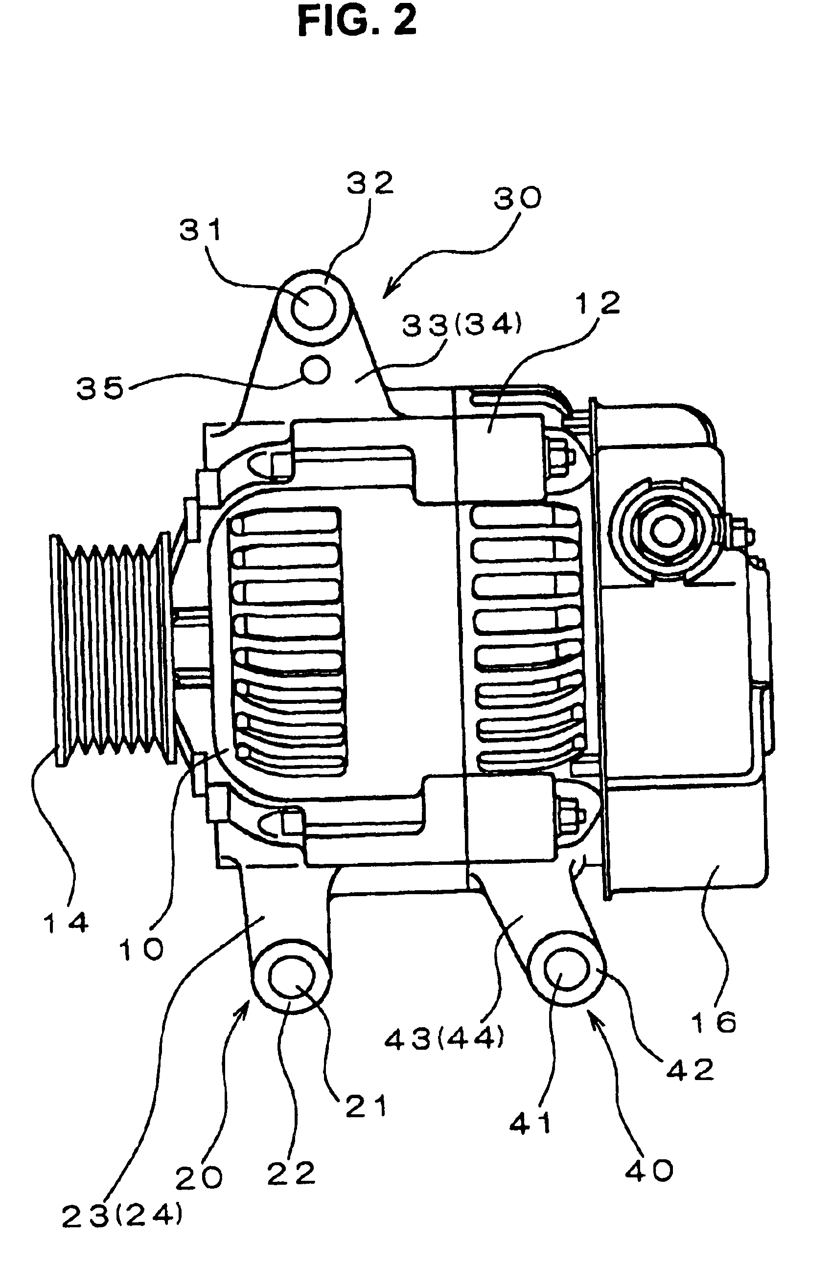
An embodiment of a vehicle-use alternator will be described in the following, referring to the drawings. FIG. 1 is a view in elevation of one end of a vehicle-use alternator 1 (referred to in the following simply as the alternator 1), while FIG. 2 is a corresponding side view in elevation. These illustrate the alternator 1 mounted on an engine block 90 of a vehicle engine, with a side-mounting configuration whereby the alternator 1 is attached to the engine block 90 by bolts which each have a central axis (i.e., longitudinal axis) oriented in a direction at right angles to the axis of rotation of the rotor of the alternator. As shown, the alternator 1 has a housing formed of a front-end housing 10 and a rear-end housing 12, which enclose a stator and rotor (not shown in the drawings). A part of one end of the shaft of the rotor extends outward from the front-end housing 10, and has a pulley fixedly attached thereon, for transmitting power from the engine to drive the rotor.

The rear-...


PUM

PropertyMeasurementUnit
axis of rotationaaaaaaaaaa
angle of tiltaaaaaaaaaa
shapeaaaaaaaaaa

Abstract

An alternator for a vehicle has a housing that is formed with attachment holes in external portions of the housing, through which a carrier jig is passed, to support the alternator when it is being mounted in the vehicle. By forming a plurality of attachment holes oriented along a common axis, at respectively different positions on the exterior of the alternator housing, it can be ensured that the carrier jig reliably holds the alternator in a required attitude as it is moved into position for mounting, e.g., to be attached to a sloping side of the engine of the vehicle.

Description

BACKGROUND OF THE INVENTION1. Field of ApplicationThe present invention relates to a vehicle-use alternator that is designed to be mounted in an automobile or truck.2. Description of Prior ArtWhen a vehicle-use AC generator (in general, simply referred to as an alternator) is to be attached, in the process of assembling a vehicle, it is necessary to hold the alternator in a suspended condition as it is being moved into the required position for being mounted on the vehicle. Various arrangements can be envisaged to enable the alternator to be supported in such a suspended condition, for example by providing protrusion portions on the exterior of the alternator with holes formed in these protrusion portions, so that the holes can be used for suspending the alternator while it is being moved into the desired position for being mounted, e.g., in a location close to the vehicle engine.In recent years, for example as described in Japanese patent No. 11-262213, pages 3˜4, FIGS. 1˜6, a side...

Claims


Application Information

Patent Timeline
Patent Type & Authority Patents(United States)
IPC IPC(8): H02K15/14H02K5/00H02K5/06
CPCH02K5/00H02K15/14Y10T29/49009
Inventor KAWANO, YUSUKE
Owner DENSO CORP
Why Eureka
Try Eureka