Color cathode ray tube

Inactive Publication Date: 2005-01-11
LG PHILIPS DISPLAY KOREA CO LTD
View PDF3 Cites 6 Cited by
  • Summary
  • Abstract
  • Description
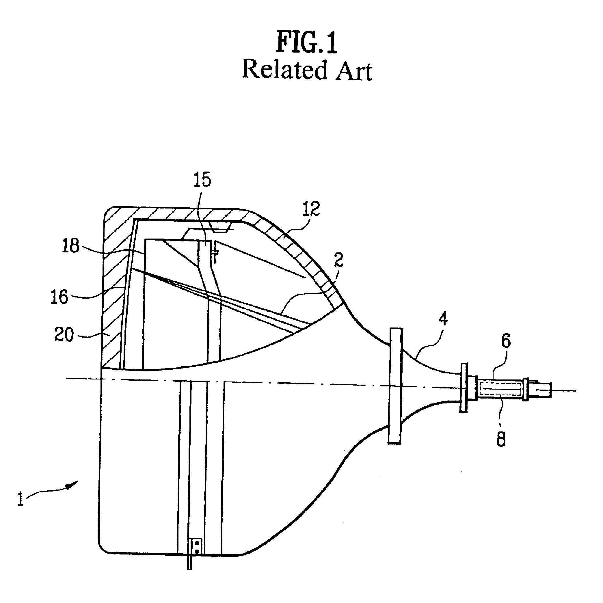
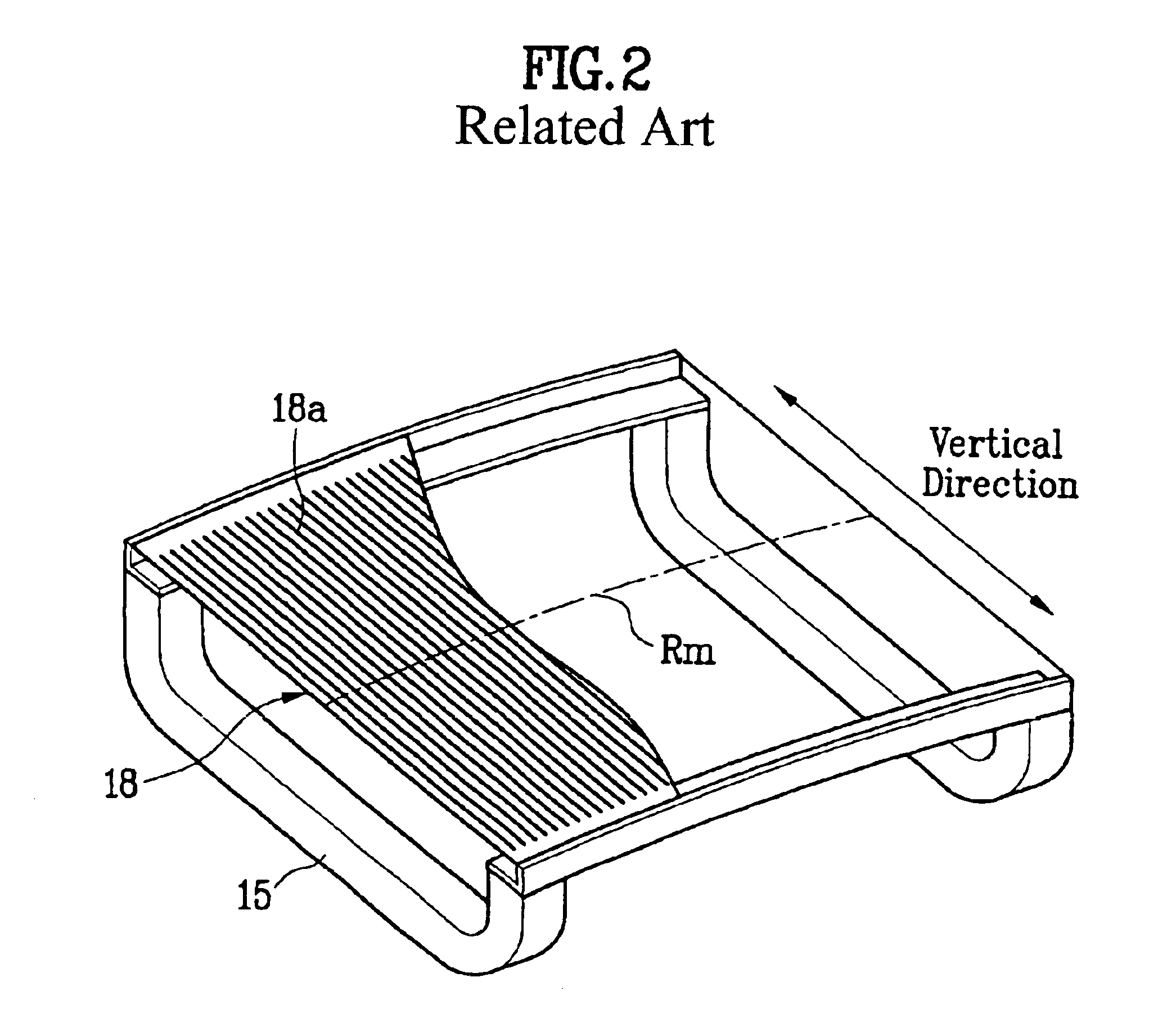
  • Claims
  • Application Information

AI Technical Summary

Benefits of technology

[0029]An object of the present invention is to provide a color cathode ray tube capable of improving the lumi

Problems solved by technology

The vacuum stress is increased by such the structure when evacuating the vacuum envelope of the cathode ray tube, thereby raising a safety problem.
According to the structure of the conventional panel, the inner curvature radius is increased to meet the increase of demanded value Q. The reduced vertical thickness of the glass is coupled to the portion from

Method used


Image

  • Color cathode ray tube
  • Color cathode ray tube
  • Color cathode ray tube

Examples


Embodiment Construction

re of a conventional panel;

[0043]FIG. 4 a perspective view illustrating the construction of an effective surface of a conventional panel;

[0044]FIG. 5a is a view illustrating a geometrical relationship of a conventional formed mask-type flat color cathode ray tube;

[0045]FIG. 5b is a view illustrating a geometrical relationship between electron beams and a panel and mask with respect to the conventional mask stretching-type flat color cathode ray tube;

[0046]FIG. 6 shows distortion of a vacuum envelope when evacuating the vacuum envelope;

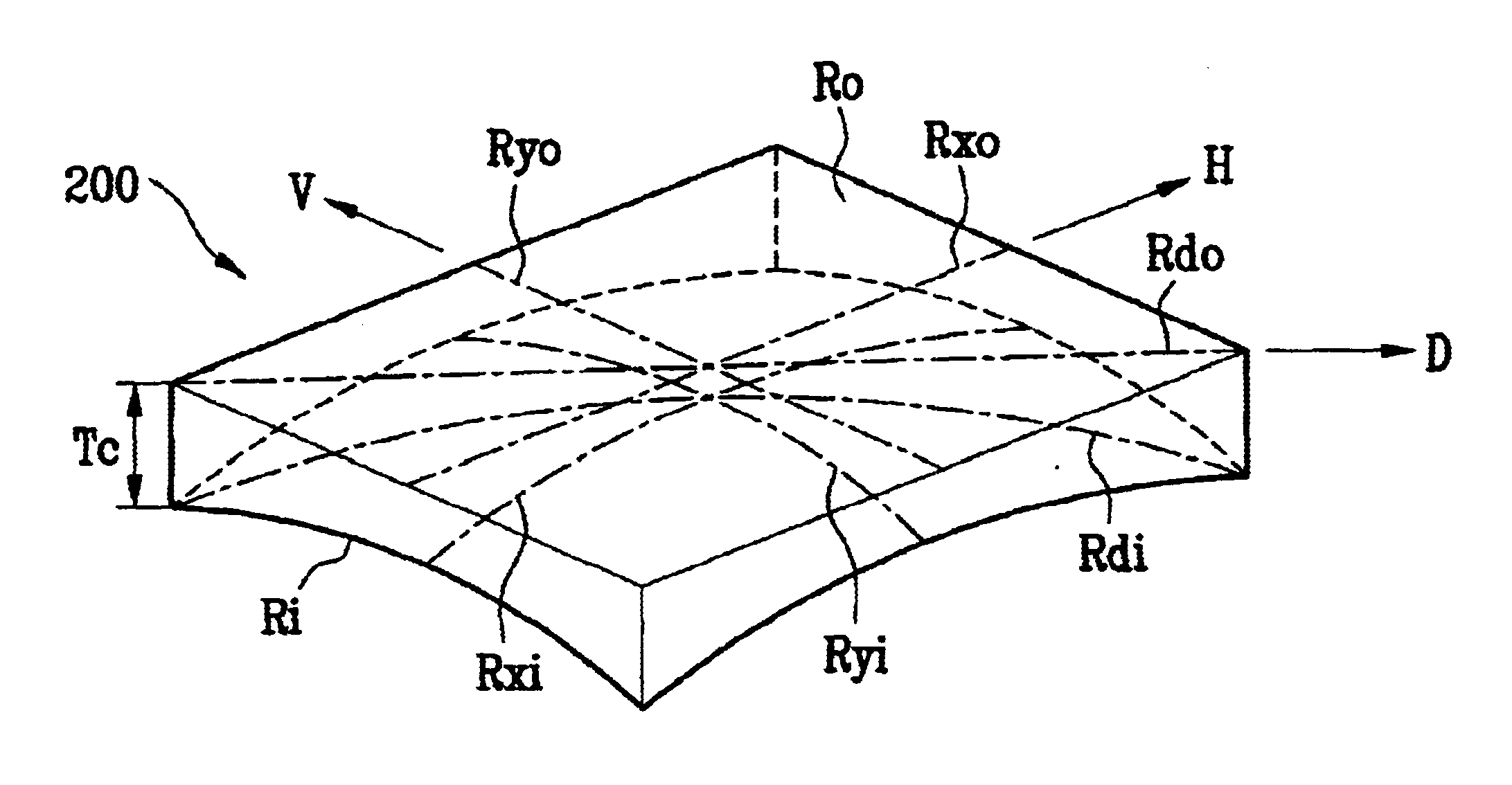
[0047]FIG. 7 is a perspective view illustrating an effective surface of a panel for a mask stretching-type color cathode ray tube;

[0048]FIGS. 8a and 8b are cross sectional views of a flat panel to which the present invention is applied; and

[0049]FIG. 9 is a view illustrating a geometrical relationship between electron beams and a panel and mask according to the present invention mask stretching-type flat color cathode ray tube.

DETAILED DESCRIPTION OF T...


PUM


Abstract

A color cathode ray tube capable of improving the luminance attenuation characteristic and the explosion-proof characteristic through an improved shape of a panel is disclosed. In an equation F=Rdo/(Sd H 1.767), F>21, Tc/CFT≦1.35, and Rdi>(Ryi or Rxi) are satisfied, wherein Sd is a length of a diagonal effective picture of the panel, Rdo is a curvature radius of a diagonal outer surface, Ryo is a curvature radius of a vertical outer surface, Rxi, Ryi and Rdi are a horizontal, vertically and diagonal curvature radius, respectively, CFT is a thickness of a center portion, Tc is a thickness of a diagonal end of the effective surface, F is a planarizing rate of the outer curvature.

Description

[0002]This application claims the benefit of the Korean Application No. P2002-00287 filed on Jan. 3, 2002, which is hereby incorporated by reference.BACKGROUND OF THE INVENTION[0003]1. Field of the Invention[0004]The present invention relates to a color cathode ray tube, and more particularly, to a color cathode ray tube capable of improving characteristics of luminance attenuation and explosion-proof through improvement of a shape of a panel.[0005]2. Discussion of the Related Art[0006]The structure of a general mask stretching-type color cathode ray tube is shown in FIG. 1.[0007]Referring to FIG. 1, a vacuum envelope consisting of a rectangular panel 20 located on its front surface, a funnel 12 located on a rear surface of the panel 20, and a neck 6 extended from a rear end of the funnel 12 is sealed in a high vacuum pressure of about 10−7 Torr to secure smooth interlaced scanning of electron beams therein. An electron gun 8 is provided in the neck 6 to emit the electron beams 2 of...

Claims


Application Information

Patent Timeline
IPC IPC(8): H01J29/86H01J29/02
CPCH01J29/861H01J2229/862H01J29/02
Inventor LEE, TAE HOON
Owner LG PHILIPS DISPLAY KOREA CO LTD
Why Eureka
Try Eureka