

Dimmable electrolumanescent lamp drivers and method therefor
a technology of electrolumanescent lamps and drivers, which is applied in the direction of electric variable regulation, process and machine control, instruments, etc., can solve the problems of limited brightness control by drive frequency, waste of energy, and circuits to control the brightness of el lamps
- Summary
- Abstract
- Description
- Claims
- Application Information
AI Technical Summary
Benefits of technology
Problems solved by technology
Method used
Image

Examples
Embodiment Construction
bject of the present invention to provide an improved EL lamp driver that is able to overcome the problems associated with the prior art EL lamp drivers.
BRIEF DESCRIPTION OF THE PREFERRED EMBODIMENTS
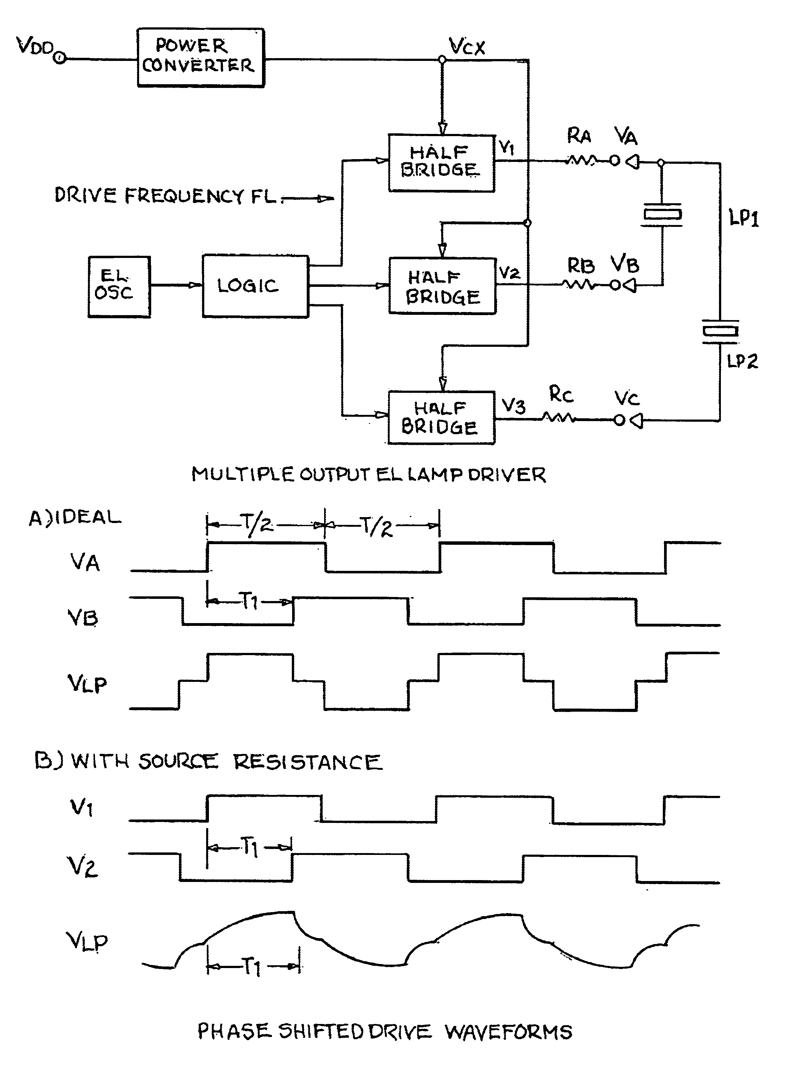
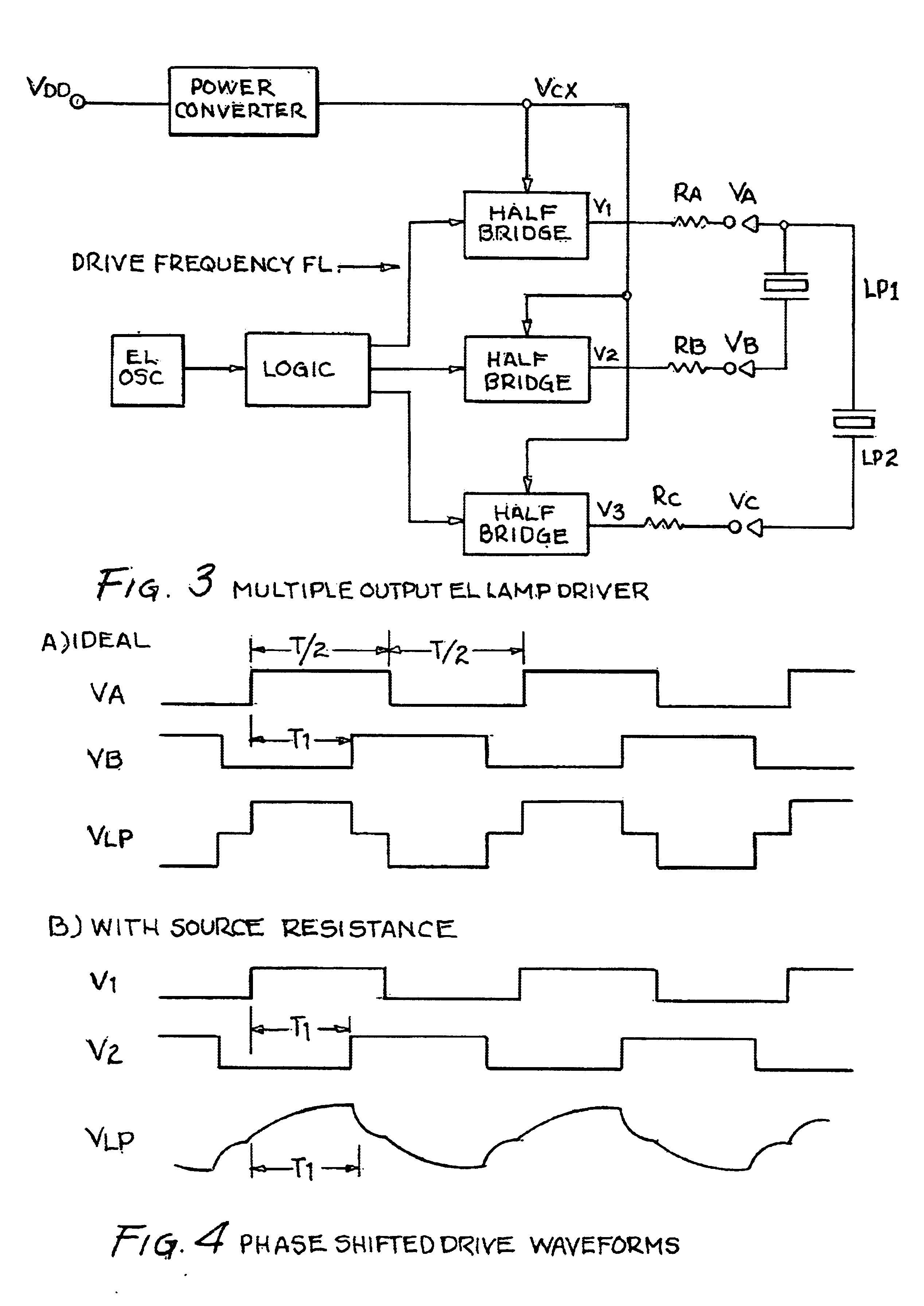
[0010]In accordance with one embodiment of the present invention a method for dimmable control of a multiple output EL lamp driver is disclosed. The multiple output EL lamp driver has a power converter. A plurality of EL lamps are provided wherein one terminal of each EL lamp is coupled to a single common terminal. A plurality of half bridge circuits are provided wherein each circuit has an output impedance. One half bridge circuit is coupled to the single common terminal and each remaining terminal of each EL lamp is coupled to a separate individual half bridge circuit. A logic circuit is coupled to each of the half bridge. An oscillator is coupled to the logic circuit. The method comprises: minimizing the output impedance of the half bridge circuit coupled to the single common terminal...
PUM
 Abstract
Description
Claims
Application Information