System and method for monitoring and indicating a condition of a filter element in a fluid delivery system

Active Publication Date: 2005-01-11
KEOWN DANIEL LEE
View PDF12 Cites 169 Cited by
  • Summary
  • Abstract
  • Description
  • Claims
  • Application Information

AI Technical Summary

Problems solved by technology

Such buildup reduces system performance and is generally difficult to remove.
Such buildup reduces the ability of the HVAC system to circulate air, and is generally difficult to remove.
As it is generally difficult to determine the condition of a filter, most filter replacements are performed on a tim

Method used


Image

  • System and method for monitoring and indicating a condition of a filter element in a fluid delivery system
  • System and method for monitoring and indicating a condition of a filter element in a fluid delivery system
  • System and method for monitoring and indicating a condition of a filter element in a fluid delivery system

Examples


Embodiment Construction

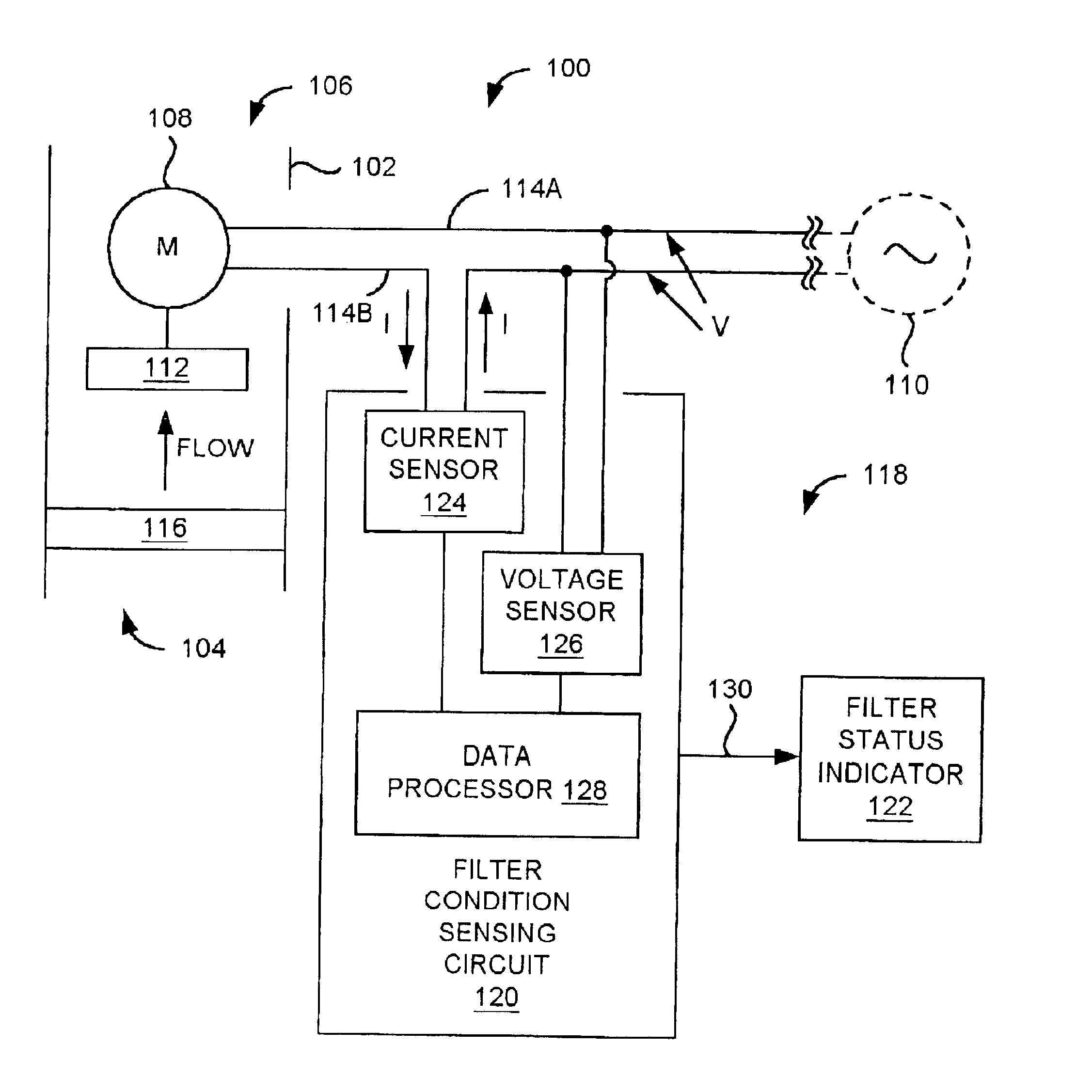
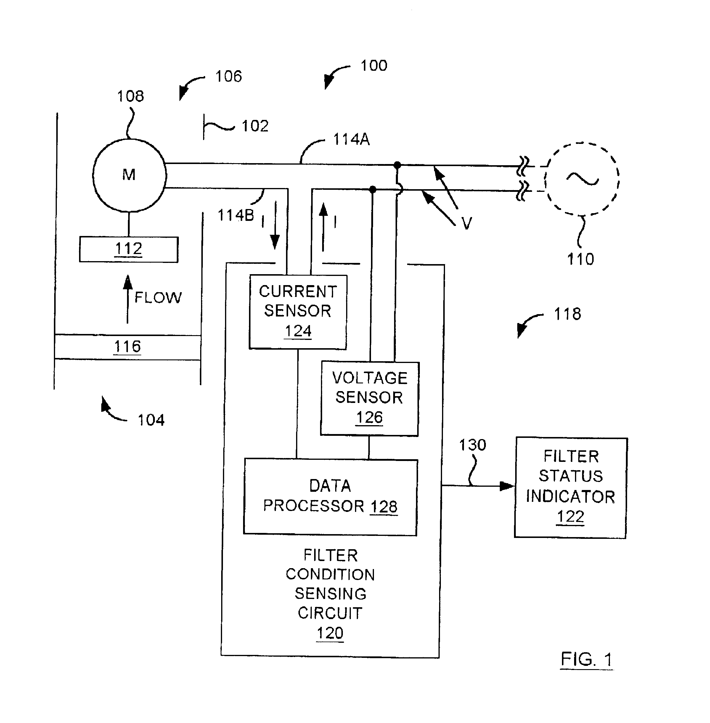
FIG. 1 is a diagram of a fluid delivery system 100 for delivering a fluid. The fluid may be, for example, a gas such as air or a liquid such as water. The fluid delivery system 100 includes a housing 102 having a fluid inlet 104 and a fluid outlet 106. Within the fluid delivery system 100, the fluid flows from the fluid inlet 104 to the fluid outlet 106 as indicated in FIG. 1.

The fluid delivery system 100 also includes a fluid flow producing device 112 for producing a flow in the fluid from the fluid inlet 104 to the fluid outlet 106. As indicated in FIG. 1, the fluid flow producing device 112 is connected to an electric motor 108. The motor 108 is connected to an alternating current (a.c.) power source 110 via a pair of conductors 114A and 114B. It is noted that a connection device (e.g., a switch or relay) would also expectedly exist between the motor 108 and the a.c. power source 110.

In general, the motor 108 converts electrical energy from the a.c. power source 110 to mechanical...


PUM

PropertyMeasurementUnit
Poweraaaaaaaaaa
Currentaaaaaaaaaa
Electric potential / voltageaaaaaaaaaa

Abstract

A filter condition sensing circuit includes current and voltage sensors and a data processor. The current and voltage sensors produce signals indicating magnitudes of electrical current and voltage, respectively, provided to an electric motor used to move a fluid (a gas or liquid) through a filter element. During a first time period, the data processor uses the signals to determine an acceptable range of electrical power required by the motor. During a second time period, the data processor uses the signals to determine a magnitude of electrical power required by the motor. When the magnitude of electrical power is within the acceptable range of electrical power, the data processor generates a signal indicating a normal condition of the filter element. A described filter condition indicating system includes the circuit. A method is for determining a condition of a filter element.

Description

BACKGROUND OF THE INVENTION1. Field of the InventionThis invention relates generally to fluid delivery systems, and more particularly to systems and methods for monitoring conditions of filter elements in fluid delivery systems.2. Description of Related ArtMany fluid delivery systems (e.g., systems for moving gases such as air and liquids such as water) include filter elements (i.e., filters) at or near fluid inlets for removing particulates from the fluid. Removing such particulates not only improves fluid quality, it also prevents the particulates from building up on system components in contact with the fluid. Such buildup reduces system performance and is generally difficult to remove. For example, a typical heating, ventilating, and air conditioning (HVAC) system includes a filter at or near an air inlet for removing particulates from the air such as dust, pollen, etc. Removing such particulates not only improves air quality, it also prevents the particulates from building up o...

Claims


Application Information

Patent Timeline
IPC IPC(8): B01D46/44B01D46/46B01D35/14B01D35/143B01D46/00
CPCB01D35/143B01D46/444B01D46/0086B01D2273/30
Inventor KEOWN, DAN LEE
Owner KEOWN DANIEL LEE
Why Eureka
Try Eureka