Eureka AIR delivers breakthrough ideas for toughest innovation challenges, trusted by R&D personnel around the world.

Motor vehicle steering system

a steering system and motor vehicle technology, applied in the direction of steering initiation, instrumentation, vessel construction, etc., can solve the problems that the steering system of the motor vehicle is not dominating the current automotive marketplace, and achieve the effect of reducing the overall cost of the steering system

Inactive Publication Date: 2005-01-11
NISSAN MOTOR CO LTD
View PDF23 Cites 13 Cited by
  • Summary
  • Abstract
  • Description
  • Claims
  • Application Information

AI Technical Summary

Benefits of technology

Accordingly, the present invention comprises a steering system selectively operable in one of three modes: steer-by-wire, electronic power assist steering (EPAS), and manual steering. The steer-by-wire system includes a driver interface system (DIS), a road wheel actuator system (RWAS), and a controller for monitoring and implementing the preferred control strategy. The control architecture of the present invention reduces the total number of sensors necessary to operate a steer-by-wire vehicle, consequently reducing the overall cost of the vehicle steering system.

Problems solved by technology

In spite of these advantages, steer-by-wire vehicles are not dominating the current automotive marketplace.

Method used


Image

  • Motor vehicle steering system
  • Motor vehicle steering system
  • Motor vehicle steering system

Examples


Embodiment Construction

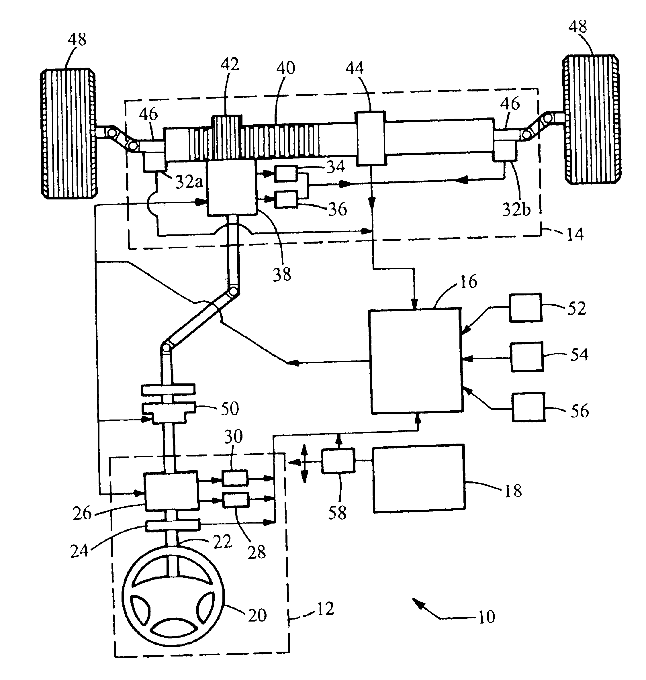
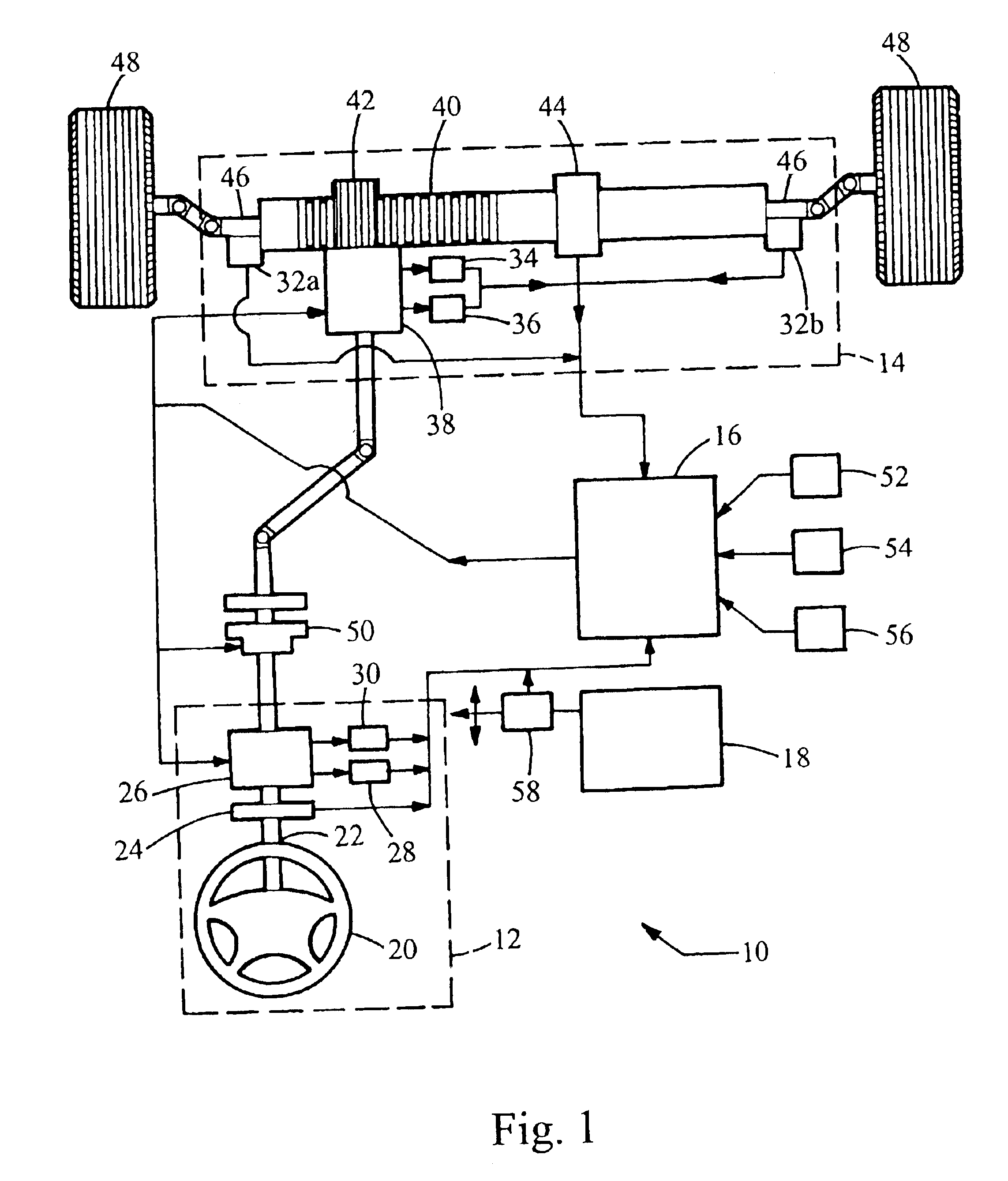
In accordance with a preferred embodiment of the present invention, FIG. 1 depicts a schematic block diagram of the steer-by-wire system 10 of the present invention. The steer-by-wire system 10 includes as its primary components a driver interface system (DIS) 12, a road wheel actuator system (RWAS) 14, and a controller 16 for monitoring and controlling the respective systems. The control architecture of the steer-by-wire system 10 of the present invention is based upon the operational independence of the DIS 12 and the RWAS 14. The steer-by-wire system 10 is powered by a battery 18, which provides electrical power to the various electrical components herein.

The DIS 12 includes a steerable member 20 that is rotatable about a shaft 22. The shaft 22 extends from the steerable member 20 towards the RWAS 14. Between the shaft 22 and the RWAS 14 is a clutch mechanism 50, the control of which is discussed further herein. The rotation of the steerable member 20 and the shaft 22 is measured...


PUM


Abstract

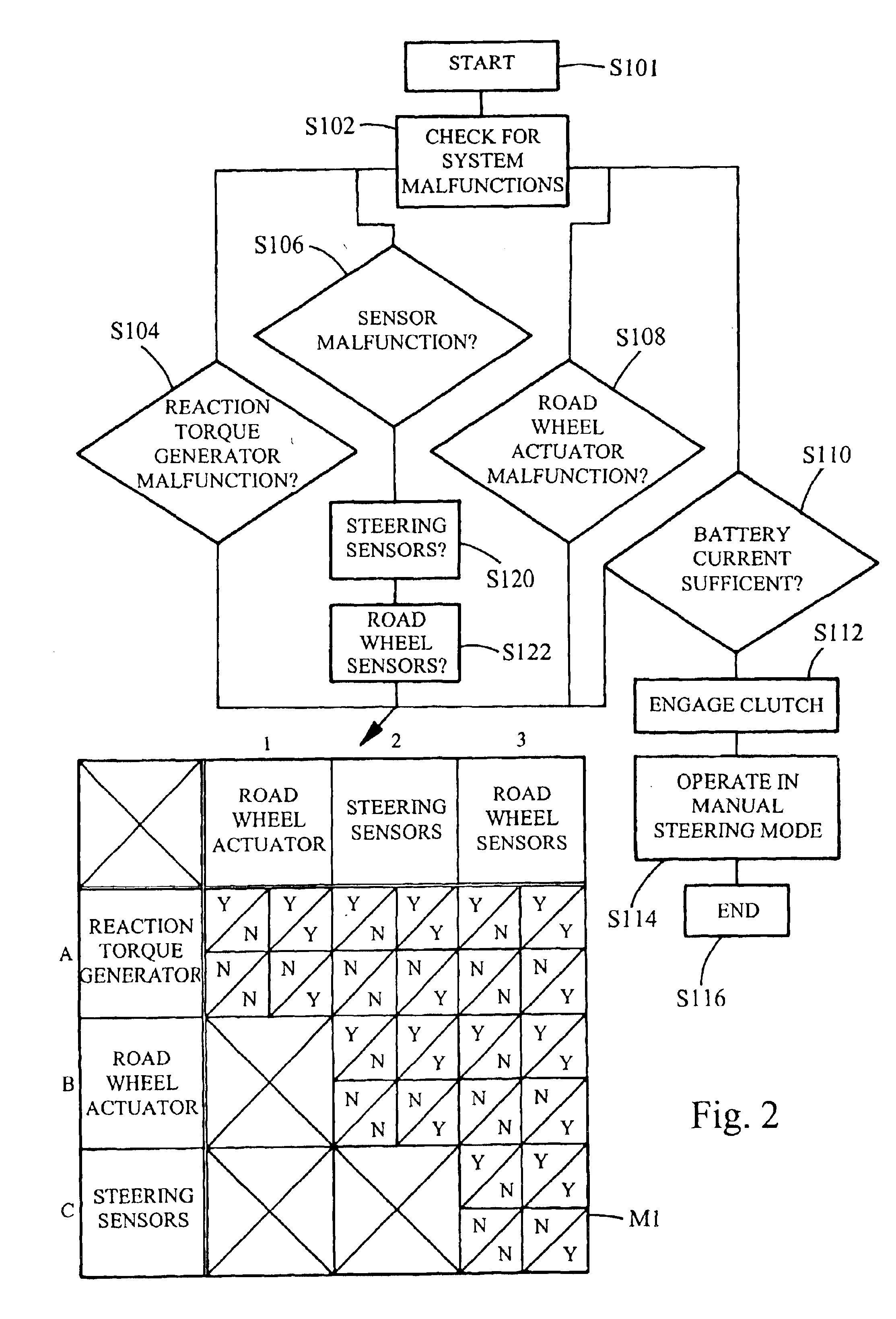
The present invention comprises a steering system selectively operable in one of three modes: steer-by-wire, electronic power assist steering (EPAS), and manual steering. The steer-by-wire system includes a driver interface system (DIS), a road wheel actuator system (RWAS), and a controller for monitoring and implementing the preferred control strategy. The steering system of the present invention operates normally in a steer-by-wire mode. In each of the EPAS mode and manual mode, the controller causes a clutch mechanism to engage, thus creating a mechanical linkage between the steerable member and the rack and pinion system. In the EPAS mode, one of the road wheel actuator or the reaction torque generator is available to assist in the steering operation. Alternatively, in the manual mode, both the DIS and the RWAS are deactivated and the vehicle is steerable through entirely mechanical means.

Description

BACKGROUND OF THE INVENTION1. Technical Field of the InventionThe present invention relates to a steering apparatus for a vehicle that directs steerable wheels in response to operator input in which the steerable wheels are not mechanically coupled to the manually steerable member.2. Description of the Prior ArtA typical automotive vehicle is steered by transmitting operations of a manually steerable member, such as a steering wheel, to a steering mechanism for directing steerable wheels for steering. Generally, the manually steerable member is located inside the vehicle passenger compartment, and the steerable wheels are located at the front of the vehicle. Thus, a suitable steering mechanism is necessary to couple the manually steerable member and the steerable wheels.A representative steering mechanism is a rack-and-pinion type steering mechanism. In a rack-and-pinion steering mechanism, the rotational motion of the steering wheel is communicated through a steering column to a pi...

Claims


Application Information

Patent Timeline
Patent Type & Authority Patents(United States)
IPC IPC(8): B62D5/04B62D5/00B62D5/06B62D6/00
CPCB62D5/003B62D5/0481B62D5/0463B62D5/006
Inventor HUSAIN, MUQTADADAUGHERTY, BRIANOYNOIAN, JOHN
Owner NISSAN MOTOR CO LTD
Why Eureka
Eureka Blog
Learn More