Method and equipment for equipping plug housings with fitted-out cable ends of a cable

Inactive Publication Date: 2005-01-18
KOMAX HOLDING
View PDF9 Cites 12 Cited by
  • Summary
  • Abstract
  • Description
  • Claims
  • Application Information

AI Technical Summary

Benefits of technology

The present invention creates a remedy for the disadvantage of the known equipment and provides an equip

Problems solved by technology

A disadvantage of this known equipment is that contacts at the cable ends twisted about the longitudinal

Method used


Image

  • Method and equipment for equipping plug housings with fitted-out cable ends of a cable
  • Method and equipment for equipping plug housings with fitted-out cable ends of a cable
  • Method and equipment for equipping plug housings with fitted-out cable ends of a cable

Examples


Embodiment Construction

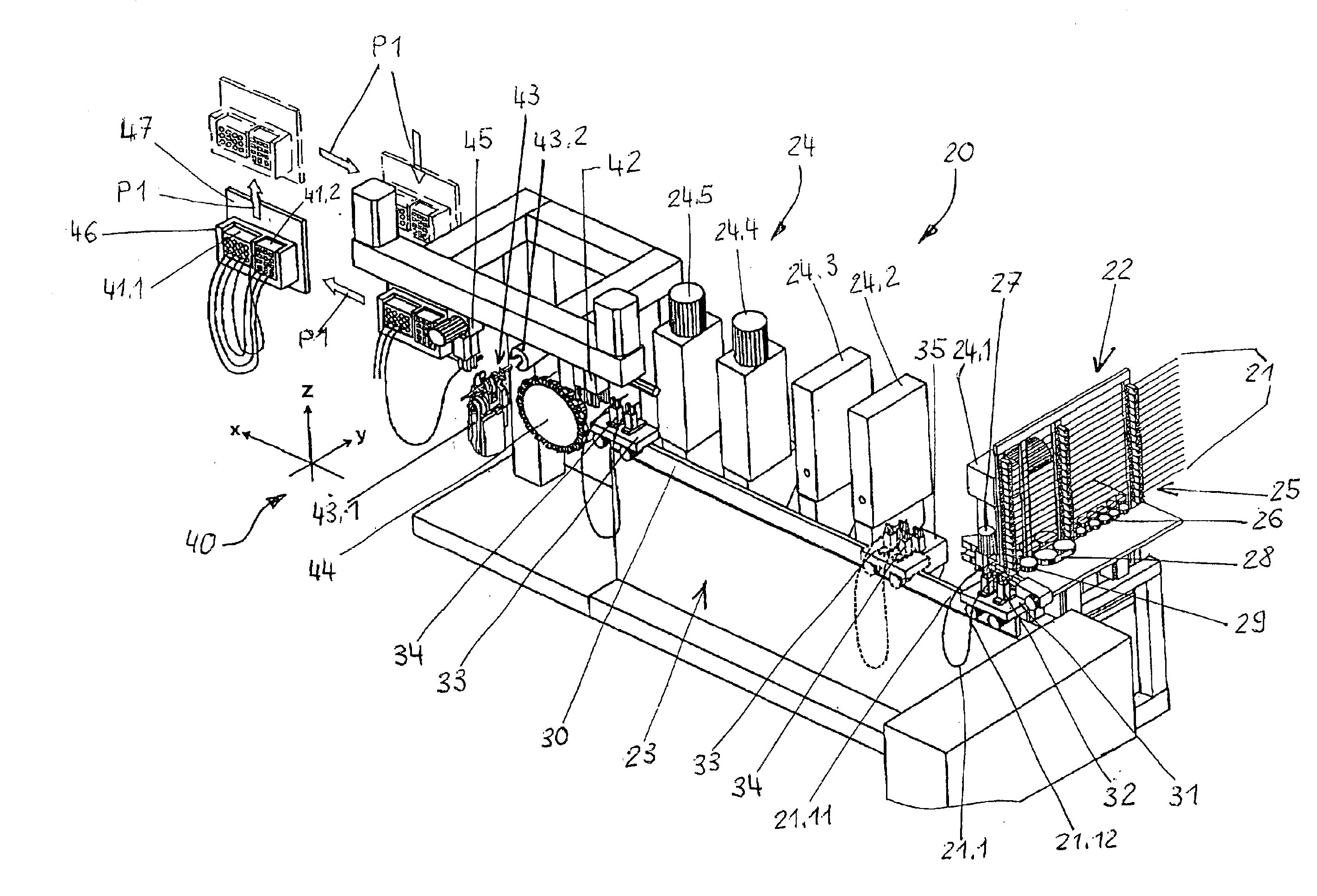
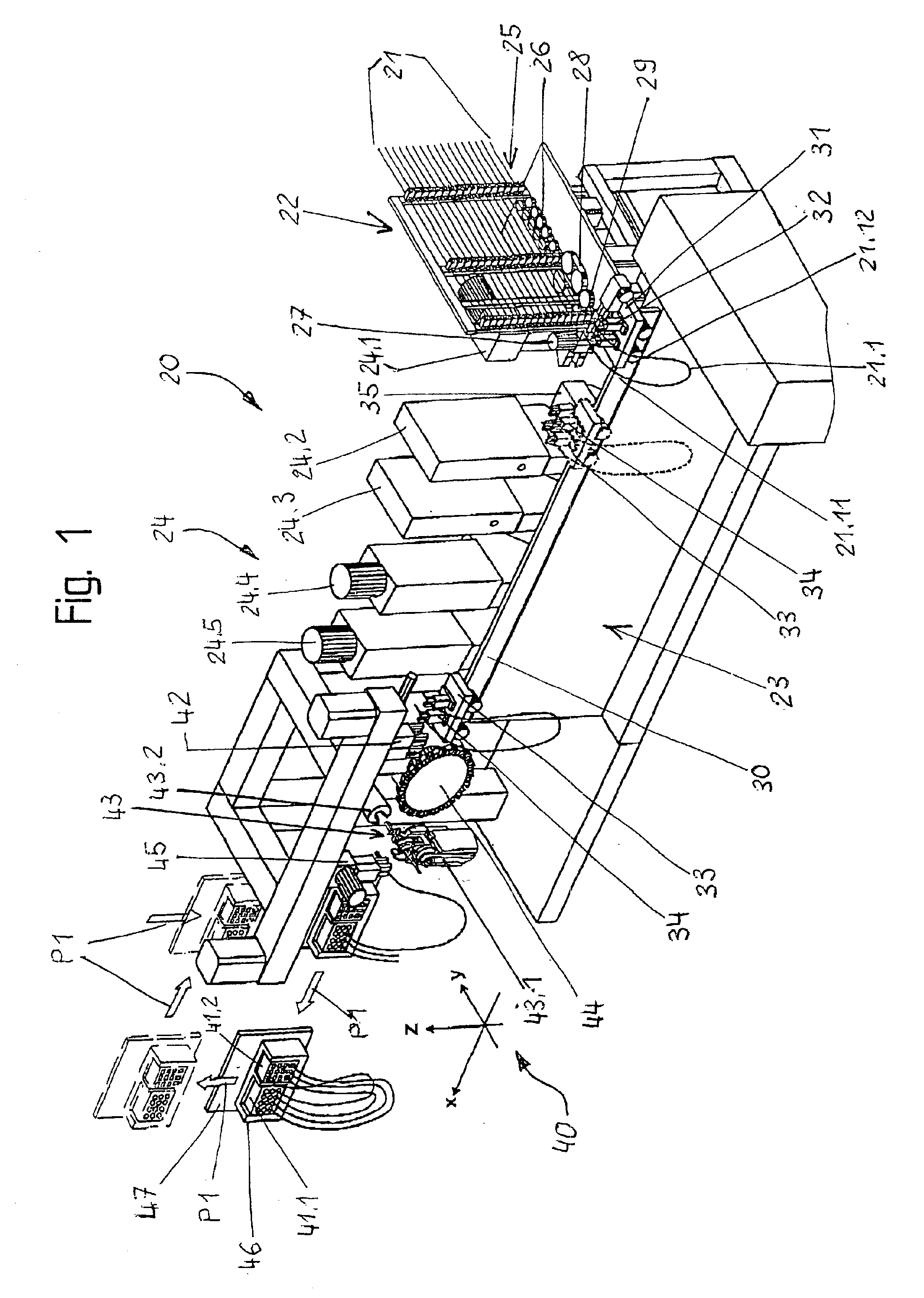
FIG. 1 shows a fitting-out installation 20 for cables 21, which includes a cable unit 22, a cable feeder 23 and a plurality of fitting-out units 24. As the fitting-out units 24 there are provided, for example, an insulation-stripping station 24.1, a pair of bushing stations 24.2 and 24.3 and / or a pair of crimping stations 24.4 and 24.5. Further and / or other forms of fitting-out stations are also possible. A plurality of the cables 21, which can be of different cross-sections, colors and construction, are held in a cable changer 25 adjustable in height. The term “cables” means cables or conductors, including optical conductors, differing in matters of construction, diameter and color. The cable type to be fitted-out is brought into a straightening path 26 by adjustment of the cable changer 25 in height. A leading cable end 21.11 is gripped by a loop-laying device 27 and turned horizontally through 180 degrees. At the same time, the cable 21 is advanced by means of a cable advancing d...


PUM

PropertyMeasurementUnit
Angleaaaaaaaaaa
Widthaaaaaaaaaa

Abstract

An equipping installation introduces fitted-out cable ends into plug housings and is arranged downstream from a fitting-out installation. A contact for the first plug housing is arranged at the leading cable end and a contact for the second plug housing is arranged at the trailing cable end. A feeder unit takes over the cable loop fitted-out to a finished state from a second transfer unit and transfers the leading cable end to a positioning unit and the trailing cable end either to a rotatable store or, after the positioning unit is again free of cable, to the positioning unit in accordance with a cable plan. An equipping unit takes over the cable ends in succession at the positioning unit and introduces the cable ends into the corresponding plug housings.

Description

BACKGROUND OF THE INVENTIONThe present invention relates to a method and equipment for equipping plug housings with fitted-out cable ends of a cable, wherein an equipping unit introduces the cable ends into cells of the plug housing.An equipping installation, which is arranged downstream of a fitting-out installation and which introduces the fitted-out cable ends in finished state into a first plug housing or into a second plug housing, is shown in the European patent application EP 0 181 0355.6. A contact for the first plug housing is arranged at the leading cable end and a contact for the second plug housing is arranged at the trailing cable end. A feeder unit takes over from a second transfer unit the cable loop fitted-out to a finished state and transfers the leading cable end to a second transfer station and the trailing cable end either to a rotatable store or, after the second transfer station is again free of cable, to the second transfer station in accordance with the respe...

Claims


Application Information

Patent Timeline
IPC IPC(8): H01R43/20
CPCH01R43/20Y10T29/49117Y10T29/49204Y10T29/5193Y10T29/5313Y10T29/49153Y10T29/49174Y10T29/49147Y10T29/49194Y10T29/514Y10T29/53235Y10T29/53213Y10T29/53261Y10T29/49004Y10T29/49208Y10T29/53217Y10T29/53209
Inventor REVEL, JEANMEISSER, CLAUDIO
Owner KOMAX HOLDING
Why Eureka
Try Eureka