Brake booster

a technology of brake booster and brake plate, which is applied in the direction of brake system, vehicle components, servomotor, etc., can solve the problems of increasing the manufacturing cost of the brake plate booster, and achieve the effects of increasing the output, simple construction, and increasing the outpu

Inactive Publication Date: 2002-05-16
DIESEL KIKI CO LTD
View PDF0 Cites 11 Cited by
  • Summary
  • Abstract
  • Description
  • Claims
  • Application Information

AI Technical Summary

Benefits of technology

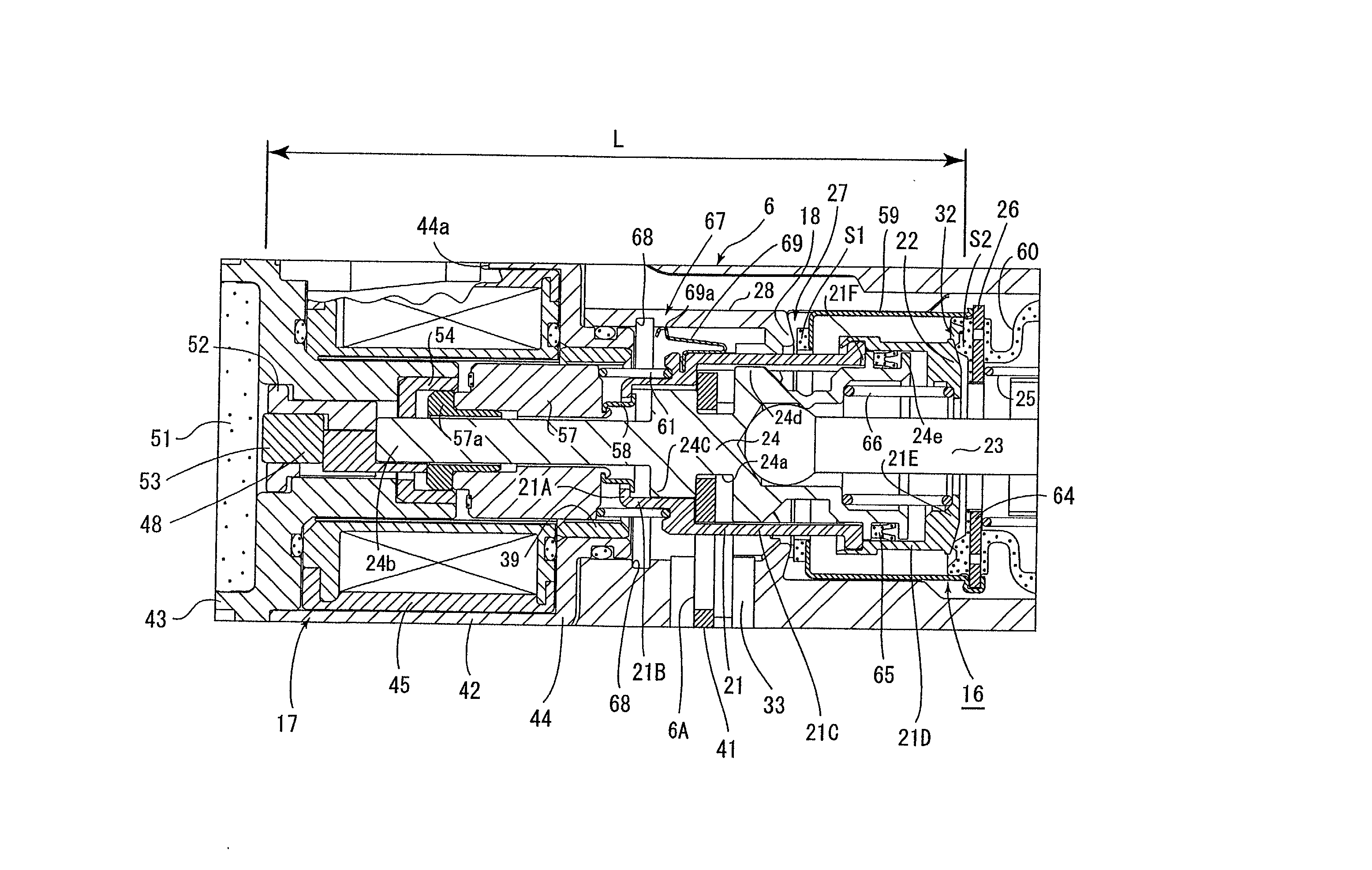
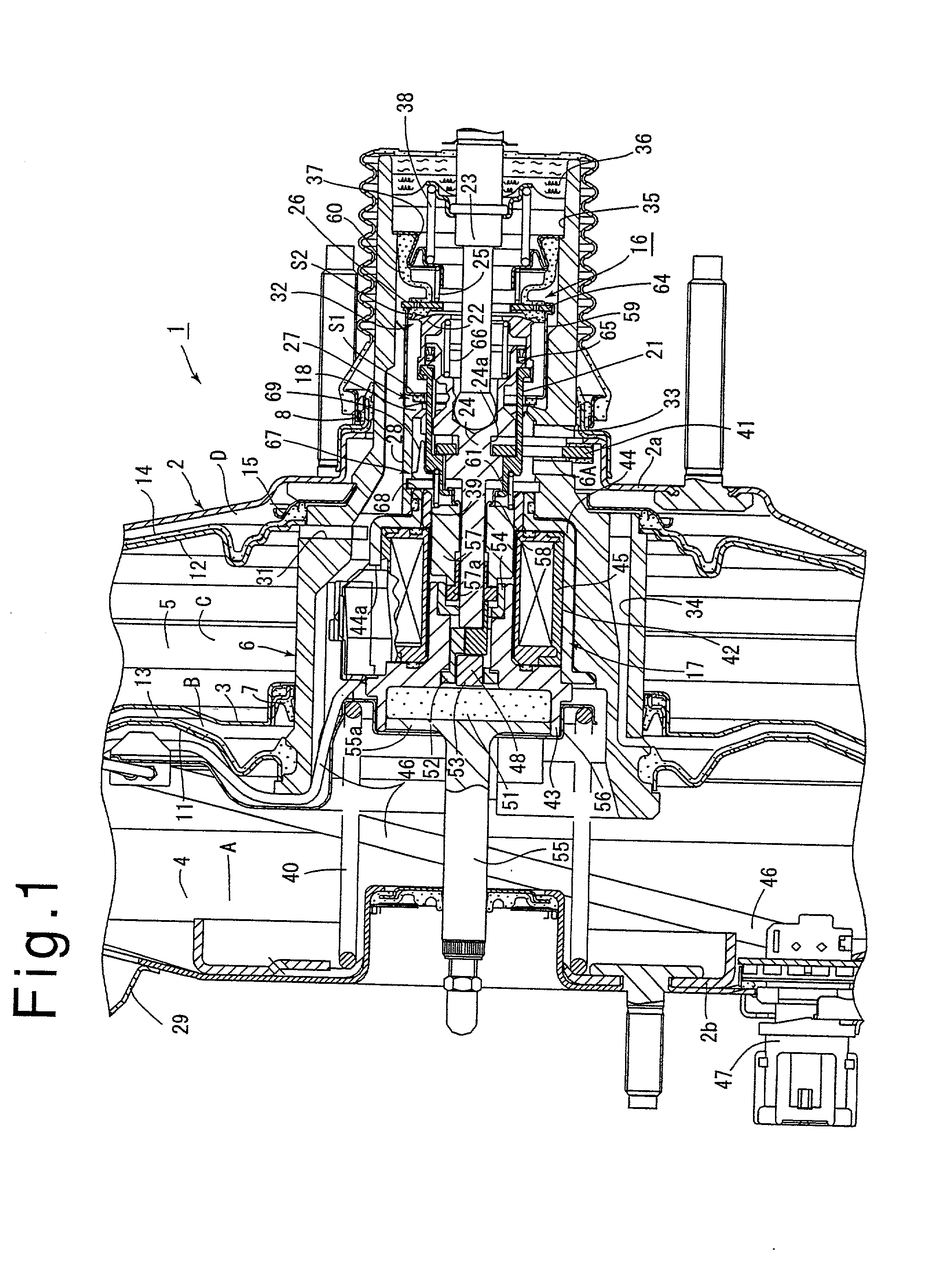
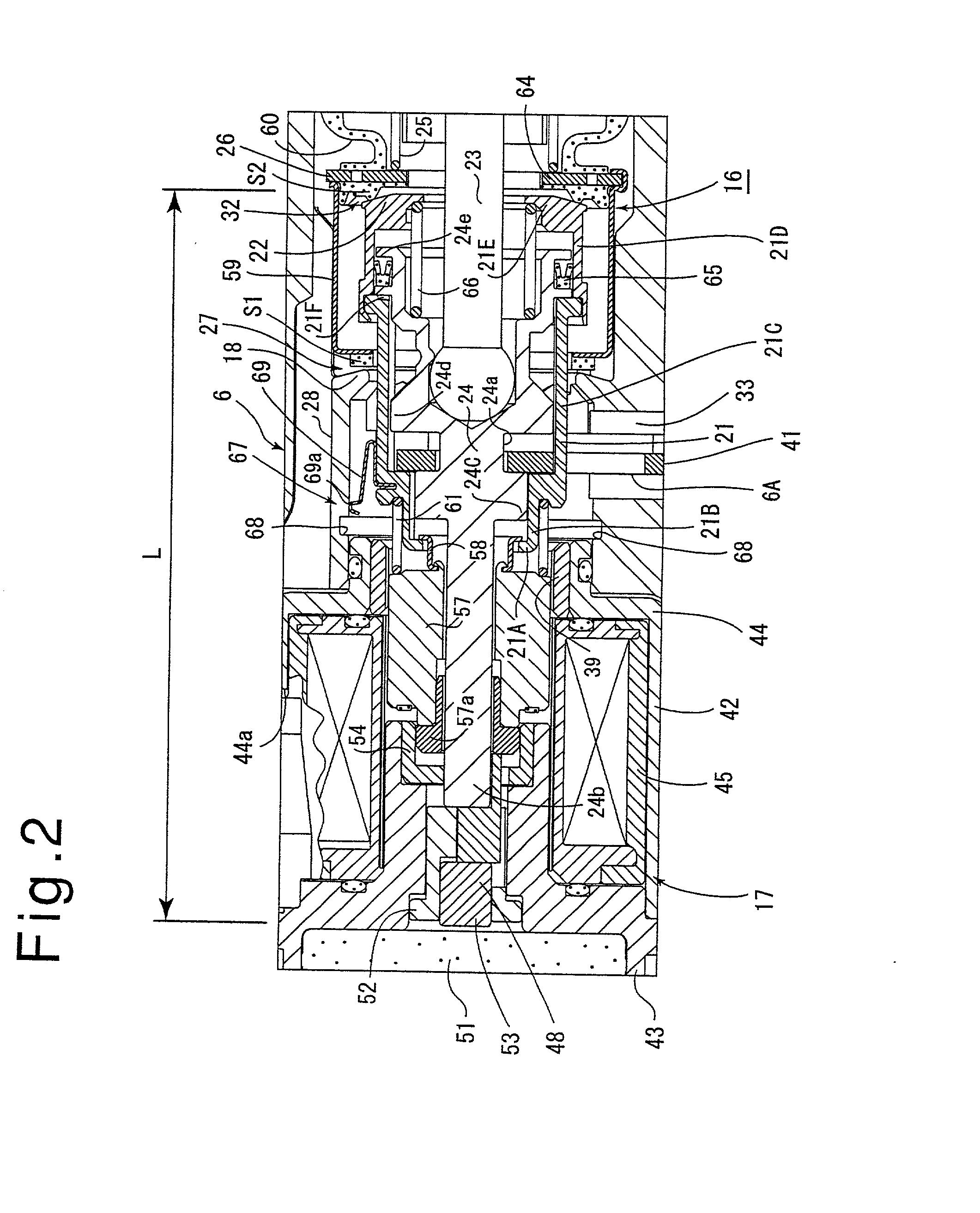
[0007] With the described arrangement, when the brake pedal is quickly depressed and the input shaft is driven forward through the given stroke relative to the valve body, the engaging means maintains the second seat of the valve element removed from the atmosphere valve seat, thereby allowing the atmosphere to be rapidly introduced into the variable pressure chamber of the brake booster to increase its output. In this manner, there is provided a brake booster which is simple in construction and which is capable of immediately increasing the output in response to a quick depression of the brake pedal.

Problems solved by technology

However, drawbacks are pointed out with conventional brake boosters as mentioned above.
In the brake booster disclosed in Application No. 35,474 / 1998, there is a need to provide a solenoid operated valve and a sensor which detects the degree of depression of the brake pedal in an integral manner with the booster, resulting in a complicated arrangement and an increased manufacturing cost of the brake booster.

Method used


Image

  • Brake booster
  • Brake booster
  • Brake booster

Examples


second embodiment

[0091] Second Embodiment

[0092] FIGS. 8 and 9 show a second embodiment of engaging means 167. In the second embodiment, engaging means 167 comprises a recess 168 formed in a tubular member 121, an engaging member 169 formed on a valve body 106, and drive means 171 which causes the engaging member 169 to be engaged with or disengaged from the recess 168.

[0093] Specifically, the recess 168 comprises an annular groove which is formed circumferentially in the outer peripheral surface of a portion 121C of a medium diameter of a tubular member 121 toward the front end thereof.

[0094] A yoke 144 has a rear portion of a reduced diameter, the axial size of which is increased and which is formed with a notch 144b at its rear end.

[0095] The engaging member 169, which is substantially triangular, is mounted in the notch 144b by a pin 172. Toward the rear end, the engaging member 169 is formed with a pawl 169a on its inner portion. The engaging member 169 is swingable radially of the yoke 144 (or ...


PUM


Abstract

A tubular member 21 is disposed within a valve body 6, and has a resilient retainer 69 mounted around the outer periphery thereof. The inner periphery of the valve body 6 is formed with an annular groove 68. When a brake pedal is quickly depressed, an input shaft 23 and the tubular member 21 are driven forward through more than a given stroke relative to the valve body, whereby a projection 69a of the retainer 69 becomes engaged with the annular groove 68. This produces and maintains a large opening in an atmosphere valve 32. Accordingly, an output from a tandem brake booster 1 can be increased immediately in response to a quick depression of the brake pedal.

Description

[0001] The invention relates to a brake booster, and more particularly, to a brake booster which assures that an increased output can be obtained in response to a force of depression of a small magnitude which is applied to an brake pedal in the event a braking effort of an increased magnitude is required as in an emergency brake.DESCRIPTION OF THE PRIOR ART[0002] A brake booster which is arranged to permit an increased output to be obtained even in response to a brake depressing force of a small magnitude as in an emergency brake which requires a braking effort of an increased magnitude is known in the art, as exemplified by Japanese Patent No. 3,070,672 disclosing a brake booster in which in response to an input which exceeds a given value, an output gradient is increased subsequently to increase the output, or a Japanese Laid-Open Patent Application No. 35,474 / 1998 disclosing a brake booster in which an operation of an brake pedal is electrically detected, and the output is incre...

Claims


Application Information

Patent Timeline
Patent Type & Authority Applications(United States)
IPC IPC(8): B60T8/32B60T13/57B60T13/72
CPCB60T8/3275B60T13/72B60T13/57
Inventor INOUE, HIDEFUMISAITO, NAOHITO
Owner DIESEL KIKI CO LTD
Why Eureka
Try Eureka