
Thermal processing apparatus for substrate employing photoirradiation

Active Publication Date: 2005-01-18
DAINIPPON SCREEN MTG CO LTD
View PDF8 Cites 216 Cited by
  • Summary
  • Abstract
  • Description
  • Claims
  • Application Information

AI Technical Summary

Benefits of technology

[0012]The chamber and the lamp house cannot be opened unless the irradiation window is shielded with the shielding plate and it follows that the shielding plate necessarily shields the irradiation window during opening, so that the lamp can be prevented from breaking during maintenance of the apparatus.
[0014]The chamber and the lamp house cannot be opened unless the irradiation window is shielded with the shielding plate for releasing the locking mechanism and it follows that the shielding plate necessarily shields the irradiation window during opening, so that the lamp can be prevented from breaking during maintenance of the apparatus.
[0015]Accordingly, an object of the present invention is to provide a thermal processing apparatus capable of preventing a lamp from breaking during maintenance of the apparatus.

Problems solved by technology

Therefore, the ions must disadvantageously be implanted beyond necessity.
In general, however, an operator may carelessly come into contact with any of the xenon flash lamps provided in the lamp house to break this lamp during maintenance of the apparatus.
The xenon flash lamps are high-priced, and much time is disadvantageously required not only for exchanging the lamp but also for re-adjusting the overall lamp house if any of the xenon flash lamps is broken.

Method used


Image

  • Thermal processing apparatus for substrate employing photoirradiation
  • Thermal processing apparatus for substrate employing photoirradiation
  • Thermal processing apparatus for substrate employing photoirradiation

Examples


second embodiment

[0020]FIG. 5 is a side elevational view schematically showing the structure of a thermal processing apparatus according to the present invention; and

[0021]FIG. 6 is an enlarged view of a locking mechanism provided in the thermal processing apparatus according to the second embodiment.

DESCRIPTION OF THE PREFERRED EMBODIMENTS

[0022]Embodiments of the present invention are now described with reference to the drawings.

first embodiment

[0023]

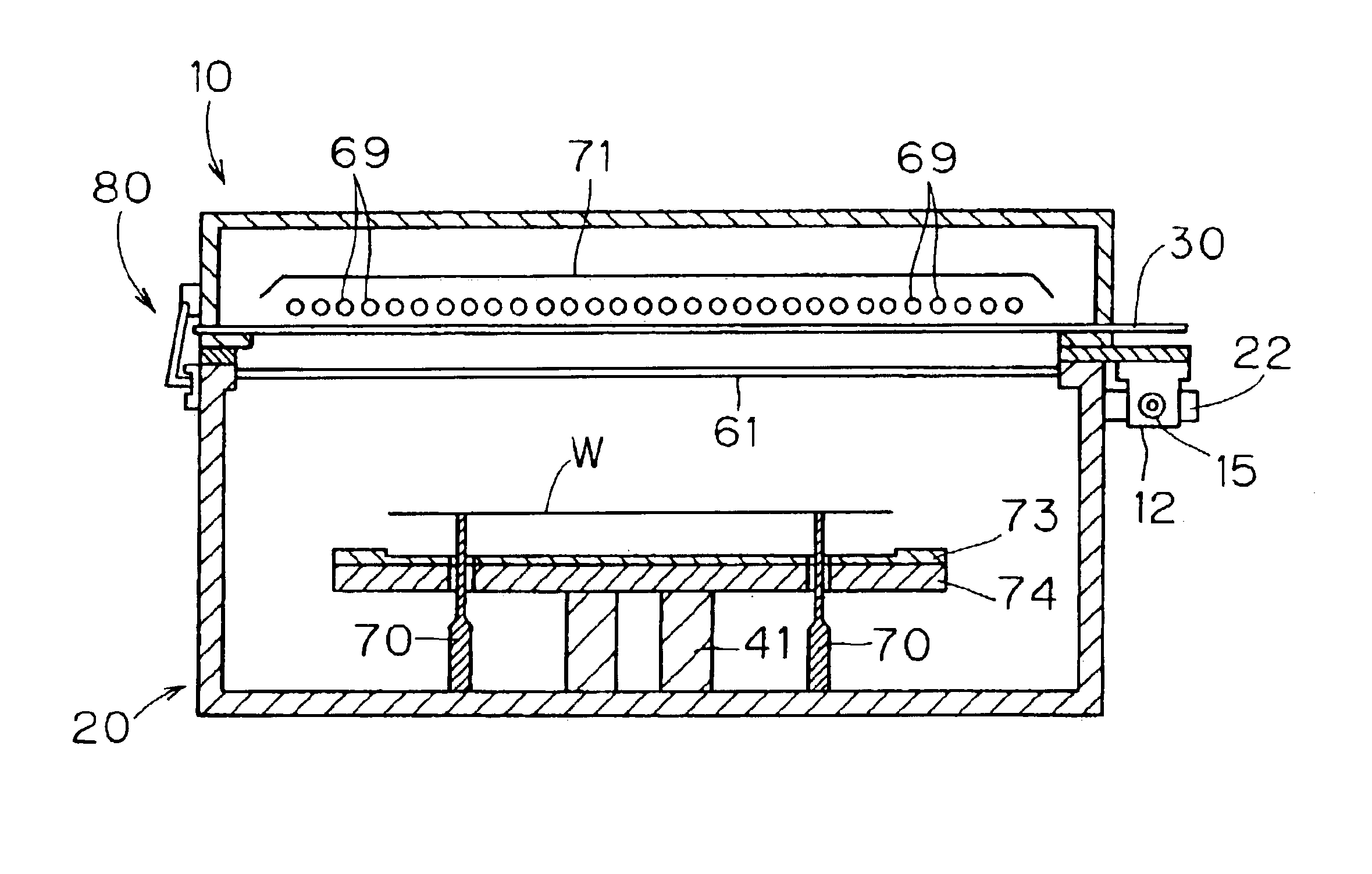
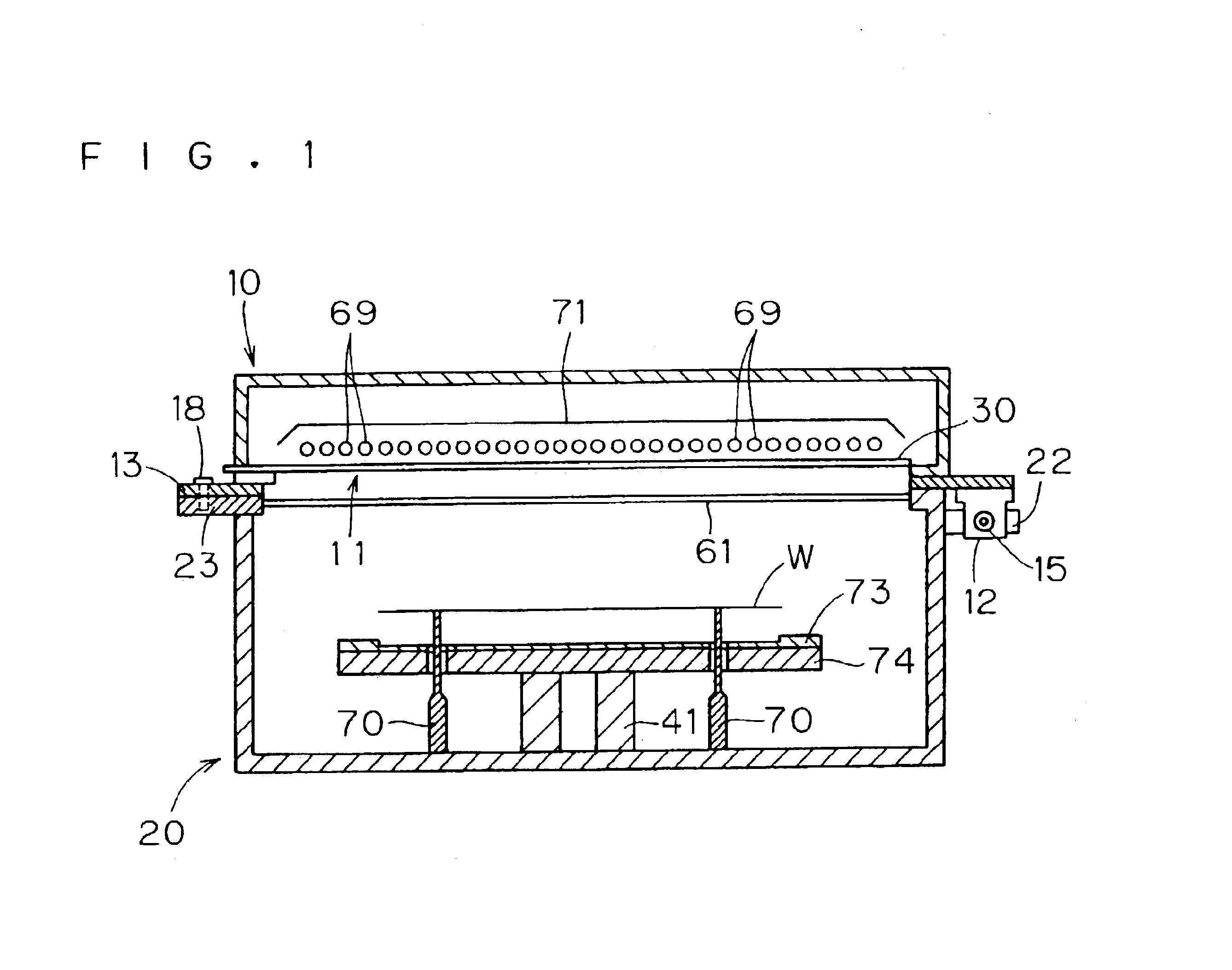
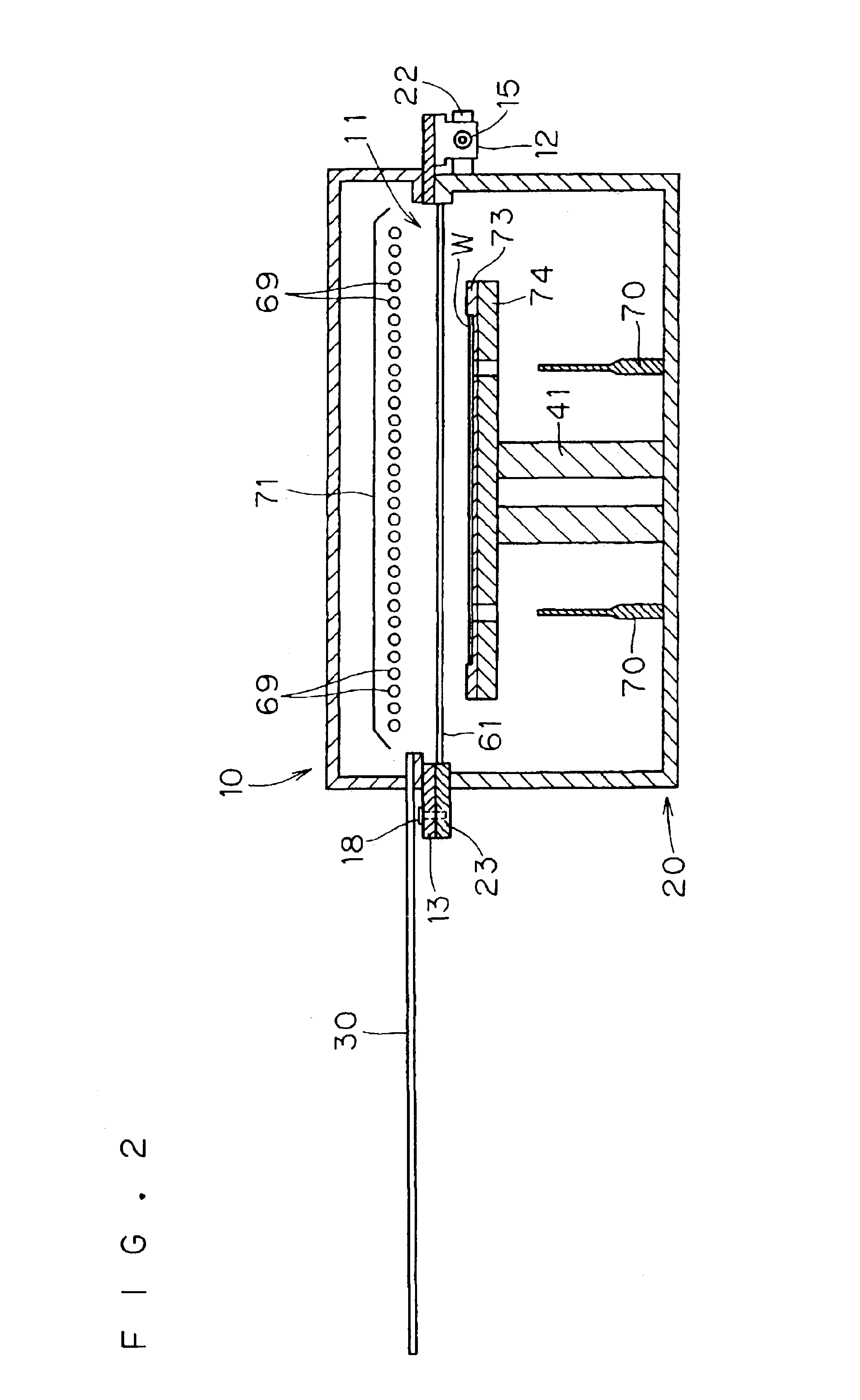
[0024]FIGS. 1 and 2 are side elevational views schematically showing the structure of a thermal processing apparatus according to a first embodiment of the present invention. This thermal processing apparatus thermally processes a substrate such as a semiconductor wafer W with flash light emitted from xenon flash lamps 69. The thermal processing apparatus is mainly formed by an upper lamp house 10 and a lower chamber 20.

[0025]The chamber 20 is employed for storing and holding the semiconductor wafer W in its housing when thermally processing the same. A translucent plate 61 forming the upper portion of the chamber 20 is made of an infrared-transparent material such as quartz, for example, for serving as a chamber window transmitting light emitted from the lamp house 10 and guiding the same into the chamber 20. Support pins 70 passing through a thermal diffusion plate 73 and a heating plate 74 described later for supporting the semiconductor wafer W from below are uprightly pro...


PUM


Abstract

A lamp house storing a plurality of flash lamps and a chamber storing and holding a semiconductor wafer are fitted to each other in an openable / closable manner. The lamp house and the chamber are fixed to a closed state with male screws. In order to process a semiconductor wafer, a shutter plate is drawn out to open an irradiation window. In this state, the shutter plate shields a space located above the male screws so that the male screws cannot be detached for opening the lamp house and the chamber. In order to open the lamp house and the chamber, the shutter plate must be inserted for shielding the irradiation window while opening the space located above the male screws. Thus, a thermal processing apparatus capable of preventing the lamps from breaking during maintenance thereof is provided.

Description

BACKGROUND OF THE INVENTION[0002]1. Field of the Invention[0003]The present invention relates to a thermal processing apparatus for thermally processing a semiconductor wafer or a glass substrate (hereinafter simply referred to as “substrate”) by irradiating the same with light.[0004]2. Description of the Background Art[0005]In general, a thermal processing apparatus such as a lamp annealing apparatus using a halogen lamp is employed in an ion activation step for an ion-implanted semiconductor wafer. This thermal processing apparatus heats (anneals) the semiconductor wafer to a temperature of about 1000° C. to 1100° C., for example, thereby carrying out the ion activation step for the semiconductor wafer. This thermal processing apparatus increases the temperature of the substrate at a rate of about hundreds of degrees per second through the energy of light emitted from the halogen lamp.[0006]However, it has been proved that the profile of ions implanted into the semiconductor wafer...

Claims


Application Information

Patent Timeline
IPC IPC(8): H01L21/00H01L21/26
CPCH01L21/67115
Inventor KUSUDA, TATSUFUMI
Owner DAINIPPON SCREEN MTG CO LTD
Learn More