Fluidic switches and methods for controlling flow in fluidic systems

a fluidic system and switch technology, applied in the field of fluidic systems, can solve problems such as system design and manufacture challenges

Inactive Publication Date: 2005-01-18
PRESIDENT & FELLOWS OF HARVARD COLLEGE
View PDF31 Cites 20 Cited by
  • Summary
  • Abstract
  • Description
  • Claims
  • Application Information

AI Technical Summary

Benefits of technology

[0011]According to another embodiment of the present invention, a method of controlling fluid flow in a fluidic system is provided including providing a fluidic system. The fluidic system includes a first fluid path having a first inlet, a second inlet and a third inlet, and a second fluid path in fluid contact with the first fluid path at a fluid contact point. The method also includes supplying a process fluid to the first inlet of the first fluid path, and supplying a carrier fluid to the second inlet of the first fluid path such that the carrier fluid forces the process fluid into a first portion of the first flow path, inhibiting switching of the process fluid to the second fluid path at the fluid contact point. The method further includes ceasing supplying the carrier fluid to the second fluid path, and supplying the carrier fluid to the third inlet of the first fluid path such that the carrier fluid forces the process fluid into a second portion of the first flow path, facilitating switching of the process fluid to the second fluid path at the fluid contact point.

Problems solved by technology

Such systems present challenges in both their design and manufacture.

Method used


Image

  • Fluidic switches and methods for controlling flow in fluidic systems
  • Fluidic switches and methods for controlling flow in fluidic systems
  • Fluidic switches and methods for controlling flow in fluidic systems

Examples


example 1

[0058]Experiments were performed to determine the effects of aspect ratio and Reynolds number on the exchange of fluid between tangential fluid paths. The flow patterns were quantified by labeling the fluid entering one of the two fluid paths with a red absorption dye ferroin (1,10-phenanthroline iron(II) sulfate complex). After the system had reached a steady state (1-5 minutes), samples (200-300 μL) of the solutions exiting from the fluid paths were collected and their optical densities were measured with a diode array UV-VIS spectrometer (Hewlett Packard) at the absorption maximum of ferroin (510 nm).

[0059]To quantify the flow through the fluid paths 20, 30 normalized quantities QS (volumetric flow rate of the fluid continuing straight through the crossing) and QT (volumetric flow rate of the fluid turning at the crossing) were calculated, where the total flow rate through both fluid paths 20, 30 was normalized to the value of 1, so that QS+QT=1. To quantify the fluid exchange be...

example 2

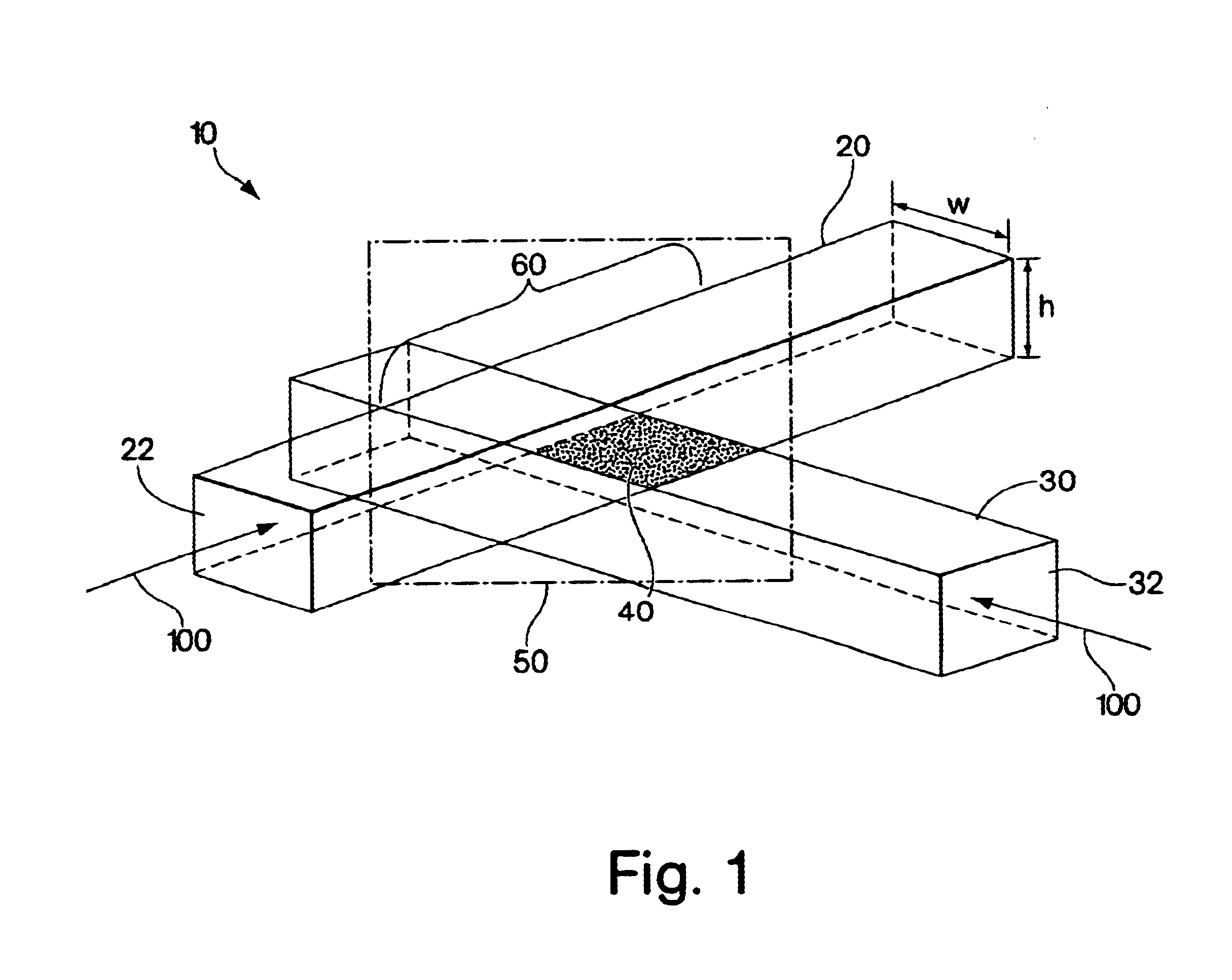
[0062]Experiments were performed to determine whether the position of a fluid within a fluid path could be successfully manipulated to create a switch. Each of the flow paths used for this experiment had three inlets, two of which were used at any one time. The flow paths measured 100 μm×40 μm. Process fluids (aqueous solutions dyed red or green) were injected through the middle inlets of each fluid path. Carrier fluid (water) was injected through either the outer or the inner inlets of the fluid paths in order to focus the width of the process fluid streams to approximately ⅙th of the width of the channel, and to position these streams within the fluid path. The Re of the fluid in the fluid paths was 10. When carrier fluid was injected through the outer inlets, the process fluid occupied the inner part of each fluid path and continued straight through the crossing region. When carrier fluid was injected through the inner inlets, the process fluid was forced to occupy the outer part...

example 3

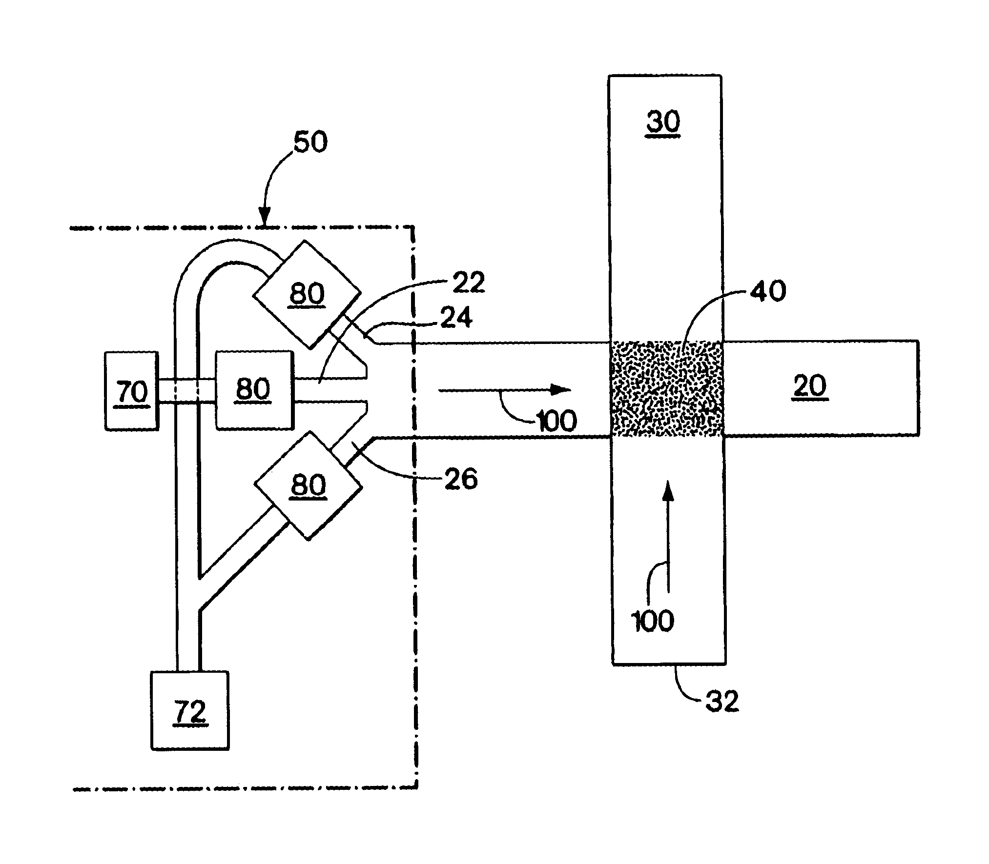
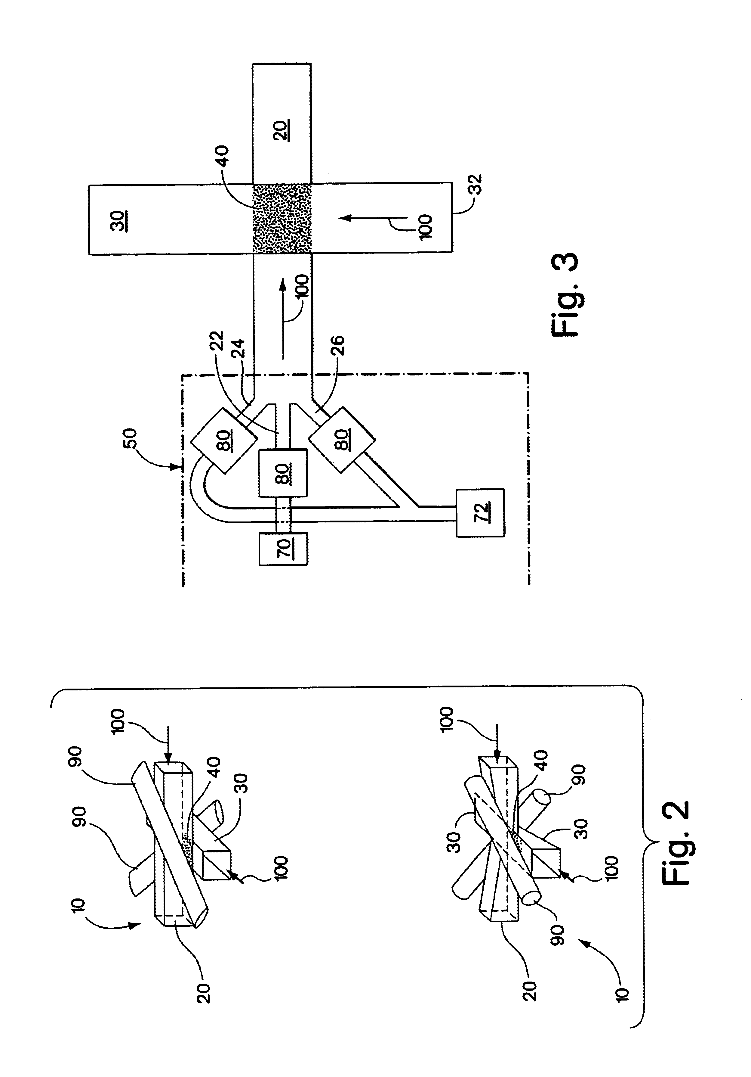
[0063]To determine whether a working switch could be constructed using the reservoir system described previously and illustrated in FIG. 2, experiments on such a system were conducted. PDMS tubes (Silastic brand, inner diameter 0.38 mm, outer diameter 1.09 mm) were molded above and below the crossing of fluid paths having a first aspect ratio of 1.2 (w×h=200 μm×240 μm). Each fluid path had three inlets, with a colored fluid being introduced into the middle inlet and carrier fluid being introduced into the outer inlets to keep the colored fluid away from the edges of the fluid path. At the crossing, colored fluid continued straight through these high aspect ratio channels. The direction of flow of the colored fluid was reversibly switched by pressurizing the PDMS tubing with air (2 atm)—the expanded PDMS tubing squeezed the channels and decreased their aspect ratio to a second aspect ratio, forcing the flow to turn. This demonstrates that a reservoir system can be used to actuate a s...


PUM


Abstract

The present invention relates to fluidic systems, including switches for fluidic systems. The switches of the present invention may be particularly applicable to microfluidic systems. The switches of the invention may include a switching region having more than one position corresponding to more than one aspect ratio. Alternatively, the switches of the invention may include multiple inlets and a system for the selective supply of carrier fluid. The present invention also relates to a method of controlling a fluid in a microfluidic system and may be performed using the switches of the present invention.

Description

RELATED APPLICATIONS[0002]This patent application claims priority to U.S. Provisional Patent Application No. 60 / 286,476, filed Apr. 25, 2001.GOVERNMENT FUNDING[0003]This invention was sponsored by the National Science Foundation Grant Number ECS9729405. The government has certain rights in the invention.FIELD OF THE INVENTION[0004]The present invention relates to fluidic systems and, in particular, switches for fluidic systems and methods for using them to control the flow in fluidic systems.BACKGROUND OF THE INVENTION[0005]Microfluidic systems are flow systems miniaturized to dimensions typically as small as a few micrometers (μm). Such systems present challenges in both their design and manufacture. For example, at the level of miniaturization of typical microfluidic systems, fluid flow is predominantly laminar. Laminar flow may also be found in other fluidic systems, such as those including viscous fluids or having low flow rates. Accordingly, the challenges presented by working ...

Claims


Application Information

Patent Timeline
Patent Type & Authority Patents(United States)
IPC IPC(8): F15C1/14F15C5/00F15C1/00F16K99/00
CPCF15C1/146F15C5/00F16K99/0001F16K99/0042F16K99/0028F16K2099/0094F16K2099/0078F16K2099/0084Y10T137/2808Y10T137/2164Y10T137/2191Y10T137/0396Y10T137/2224
Inventor ISMAGILOV, RUSTEM F.KENIS, PAUL J. A.WHITESIDES, GEORGE M.ROSMARIN, DAVID
Owner PRESIDENT & FELLOWS OF HARVARD COLLEGE
Why Eureka
Try Eureka