Pressure relief system with supply activated valve

a technology of pressure relief system and activated valve, which is applied in the direction of valve operating means/releasing devices, functional valve types, transportation and packaging, etc., can solve the problems of mechanical failure, inability to adjust the pressure response member, and inability to adjust the pressure response level. , to achieve the effect of accurate control

Inactive Publication Date: 2005-01-18
TAYLOR INNOVATIONS
View PDF21 Cites 29 Cited by
  • Summary
  • Abstract
  • Description
  • Claims
  • Application Information

AI Technical Summary

Benefits of technology

Because of the isolation of the pressure response assembly from the actuator assembly, forces associated with the valve assembly are also isolated from the actuator assembly prior to and during the initial stages of mechanical failure, allowing the threshold pressure at which mechanical failure of the member begins to be accurately controlled.

Problems solved by technology

Such pressure relief systems often use a pressure responsive member that mechanically fails when subjected to a large increase in fluid pressure.
While operable, under certain circumstances system forces can undesirably affect a threshold pressure level at which the pressure responsive member begins to fail.

Method used


Image

  • Pressure relief system with supply activated valve
  • Pressure relief system with supply activated valve
  • Pressure relief system with supply activated valve

Examples


Embodiment Construction

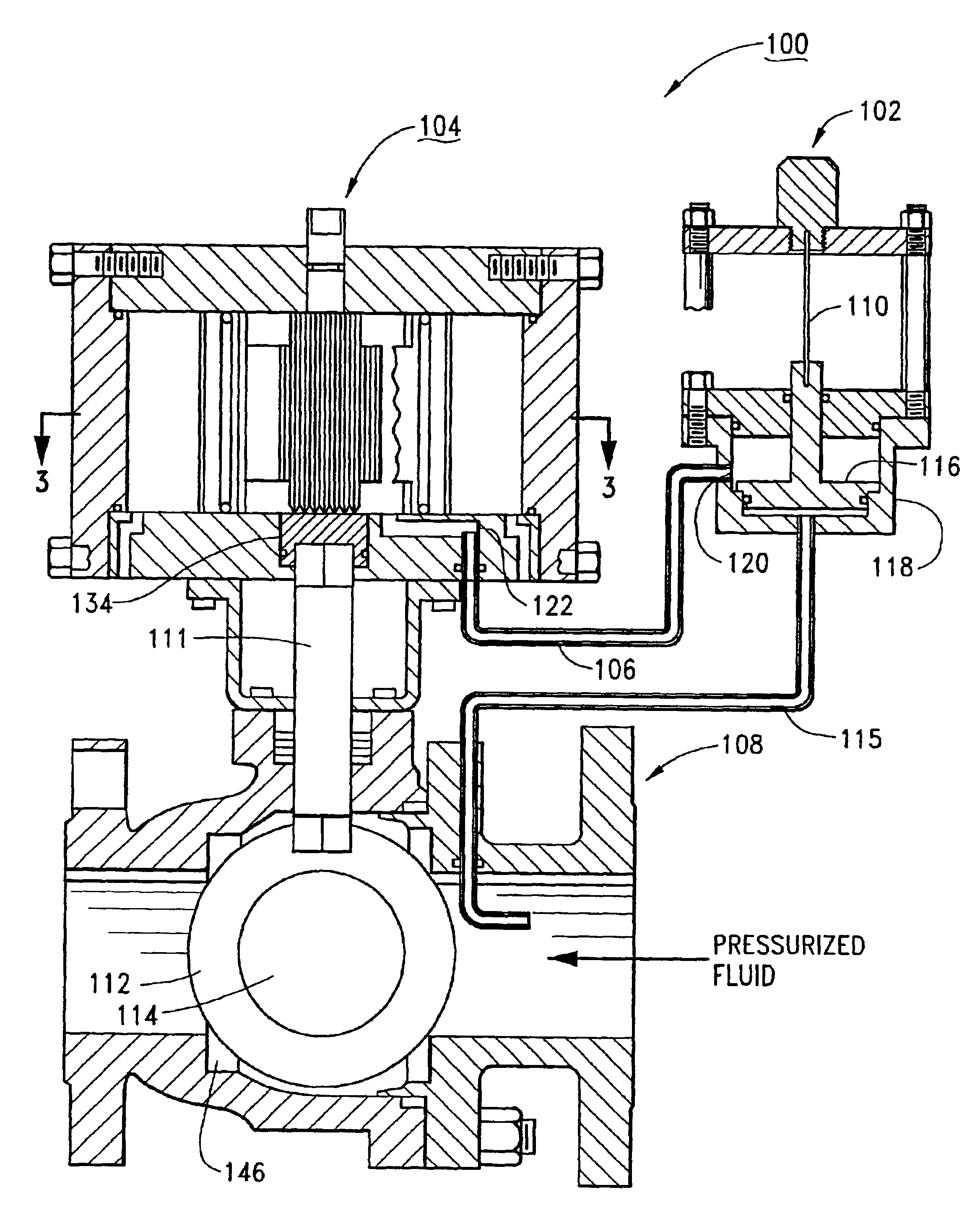
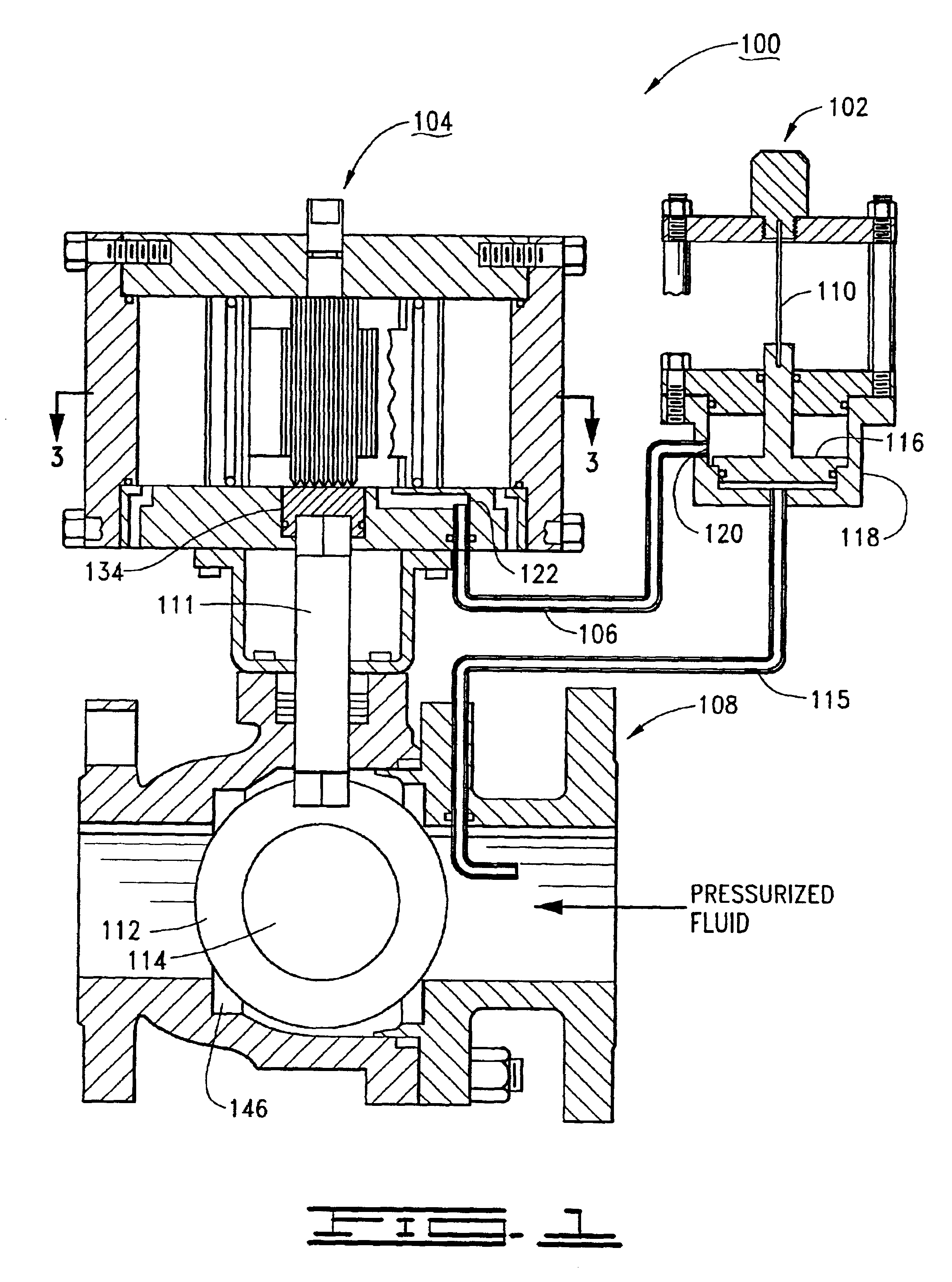
Reference is now made to FIG. 1 which shows a pressure relief system 100 constructed in accordance with preferred embodiments of the present invention. The pressure relief system 100 (“system”) is preferably used as part of a larger pressurized fluid system in which a pressurized fluid is transported. The pressure relief system 100 is used to detect an overpressure situation with the fluid and to provide an emergency overpressure path for the fluid to reduce the possibility of injury to humans and damage to equipment.

The system 100 is shown to generally include a pressure response assembly 102, an actuator assembly 104, a communication path 106 and a bypass valve assembly 108. The pressure response assembly 102 is shown to preferably comprise a buckling pin 110, although it is contemplated that other pressure responsive members can be used such as a shear pin or a frangible disk. The valve assembly 108 is shown to comprise a valve shaft 111 and a ball valve 112 with a central port 1...


PUM


Abstract

A pressure relief system for detecting and abating an overpressure in a pressurized fluid. The system includes a pressure response assembly that has a pressure responsive member, such as a buckling pin, configured to buckle when a predetermined force is applied to the member. When the buckling pin buckles, a piston slides to expose an inlet to a communication path to an actuator assembly. The actuator assembly includes a pair of sliders that move from a retracted position to an extended position when pressurized fluid enters an actuator assembly housing. The sliders have a rack that turns a pinion when the sliders move from the retracted position to the extended position. The pinion is rigidly attached to a rotatable actuator shaft. Rotation of the actuator shaft causes a valve assembly to open or close to direct the pressurized fluid through an overpressure path.

Description

FIELD OF THE INVENTIONThe present invention relates generally to pressurized fluid systems and more particularly, but not by way of limitation, to a pressure relief system which uses supply pressure to activate an actuator assembly to open or close a valve assembly.BACKGROUNDPressurized fluid systems are typically provided with pressure relief capabilities to prevent the possibility of injury to humans and damage to equipment in the event of an overpressure situation. Such pressure relief systems often use a pressure responsive member that mechanically fails when subjected to a large increase in fluid pressure.A particularly advantageous pressure relief system uses a buckling pin arrangement such as taught by U.S. Pat. No. 4,724,857 issued to Taylor. In such a system, the pin is placed under compressive load along an axial length of the pin by the pressure of the fluid. A sufficient increase in fluid pressure above a nominal operational level causes the pin to buckle, or collapse, a...

Claims


Application Information

Patent Timeline
Patent Type & Authority Patents(United States)
IPC IPC(8): F16K31/54F16K31/16F16K31/163F16K31/44F16K17/00F16K17/40
CPCF16K17/406F16K31/54F16K31/1635Y10T137/1632Y10T137/1782Y10T137/7762Y10T137/7769
Inventor TAYLOR, JULIAN S.
Owner TAYLOR INNOVATIONS
Why Eureka
Try Eureka