
Coupler for low pressure piping system

a technology for vacuum piping and couplers, which is applied in the direction of hose connections, screw threaded joints, cable terminations, etc., can solve the problems of reducing and affecting the installation effect of the coupler, so as to reduce the chance of leakage and increase the strength of the coupler

Inactive Publication Date: 2005-01-18
H P PROD
View PDF28 Cites 42 Cited by
  • Summary
  • Abstract
  • Description
  • Claims
  • Application Information

AI Technical Summary

Benefits of technology

Advantages of the invention include providing a coupler for a low pressure piping system which is seamless, thus reducing the chance of leakage and increasing the coupler's strength.
Another advantage is a coupler for a low pressure piping system of simple construction, which achieves the stated features in a simple, effective and inexpensive manner, and which solves problems and satisfies needs existing in the art.

Problems solved by technology

However, such dust has a tendency to explode.
These metal straps add cost to the coupler and can also push seals out of place during installation.
In high vibration areas, piping can vibrate out of a coupling, breaching the system.

Method used


Image

  • Coupler for low pressure piping system
  • Coupler for low pressure piping system
  • Coupler for low pressure piping system

Examples


second embodiment

the present invention is shown in FIGS. 9-10 and includes a coupler 101. Coupler 101 is similar to coupler 1 in many respects, except that V-shaped slots 112 replace elongated slots 12. Slots 112 have the point of the V facing away from end 10 and toward radial flange 14.

third embodiment

the present invention is shown in FIG. 11 and includes a coupler 201. Coupler 201 is similar to coupler 1, except there is no flared peripheral edge 11 defining open end 10, and slots 212 have open ends 213 that communicates with open end 10 and do not extend into radial flange 14.
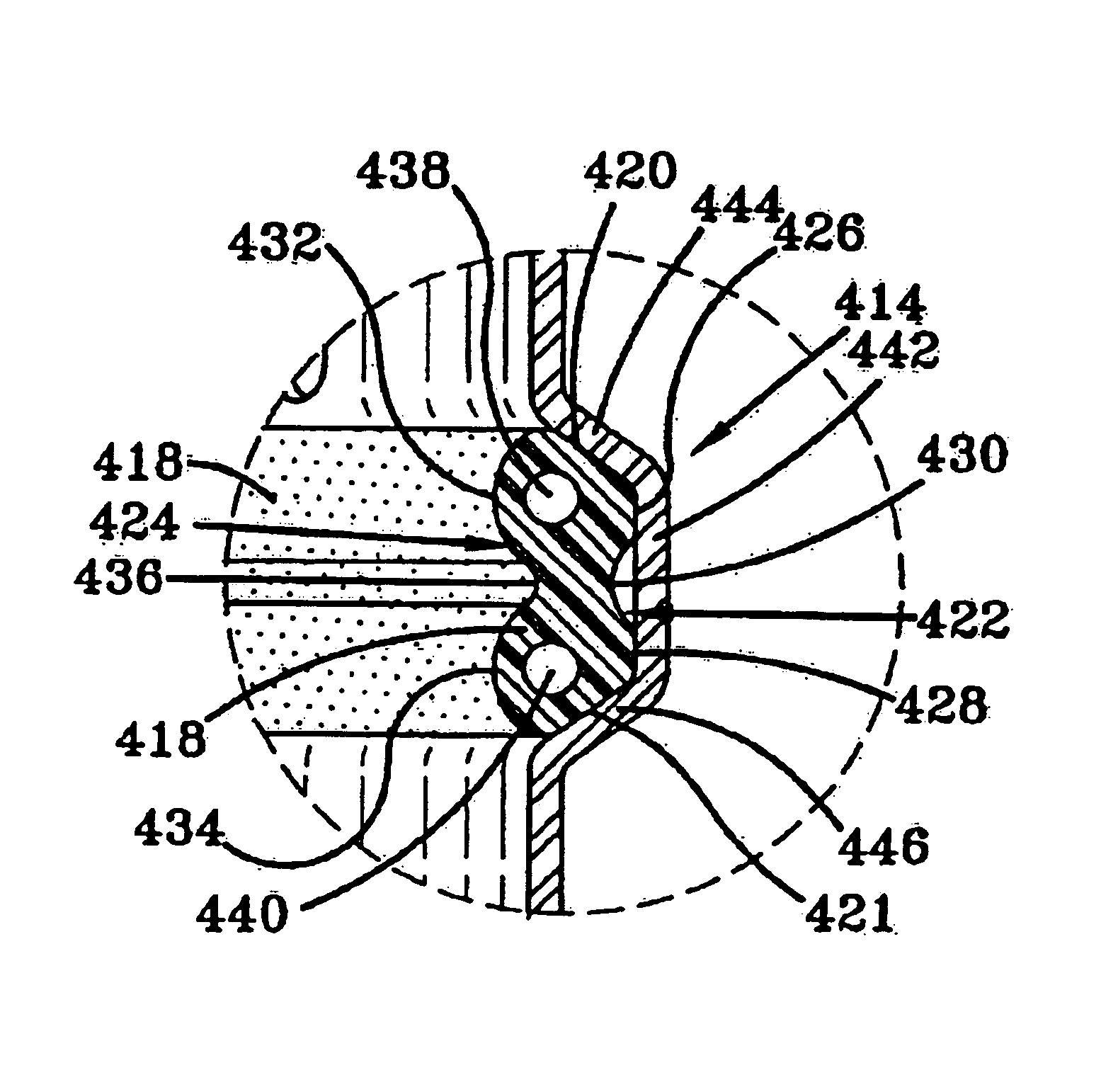
fourth embodiment

the present invention is shown in FIGS. 12-13 and includes a modified coupler 301. Coupler 301 is similar to coupler 1, except that it has a modified radial flange 314 and annular seal 318. Annular seal 318 in cross-section is substantially trapezoidal, having a long parallel side 320 and a short parallel side 322, and a pair of tapered sides 324 and 326. Sides 320 and 322 extend parallel to axis 5 when seated within a complementary shaped interior of flange 314. Seal 318 has a hollow interior 330 and includes a blade 332 which extends medially and perpendicularly from long parallel side 320 inwardly therefrom. Blade 332 has elongated parallel sides 334 which extend perpendicularly from side 320 and has a flat terminal short edge 336 which is parallel to side 320 (FIG. 13).

Radial flange 314 is generally U-shaped in cross section and has a bottom 338 and a pair of tapered sides 340 and342. Bottom 338 is parallel to axis 5, and sides 340 and 342 extend obliquely from bottom 338.


PUM


Abstract

A coupler for a low pressure piping system has a hollow metal tube terminating in a pair of end portions defining open ends for slidably receiving and joining together sections of other metal tubes in a substantially air tight relationship. Slots are formed in at least one of the end portions to aid in the crimping of the hollow metal tube by an annular clamp. A radial flange is formed adjacent the end portion and receives an annular seal therein. A stop for limiting the insertion of a tube section into the end of the hollow metal tube is formed on the inside of the coupler adjacent the radial flange opposite the slots. The annular clamp encircles the slots and is tightened to clamp the end portions to form metal to metal contact between the metal tubes and to form a seal between the annular seal and both metal tubes.

Description

BACKGROUND OF THE INVENTION1. Technical FieldThe invention relates to an improved coupler for a piping system. More particularly, the invention relates to a coupler for a low pressure or vacuum piping system for transporting materials with air. Specifically, the invention relates to a coupler generally made of a hollow metal tube and configured to receive another metal tube and clamp down on the other tube to create metal to metal contact between the two tubes and a seal between the tubes, and to an improved annular seal inserted in the hollow metal tube.2. Background InformationIn the past, vacuum and pressure pipes which were used for transporting material, such as tobacco or fine dust from wood shops or flour mills, etc. have been held together with coupling systems. However, such dust has a tendency to explode. Therefore, metal straps have been used in couplings having rubber gaskets to assure that metal to metal contact exists for grounding. These metal straps add cost to the c...

Claims


Application Information

Patent Timeline
IPC IPC(8): F16L21/06
CPCF16L21/06
Inventor BISHOP, JOHN P.CALDERONE, GREGORY A.DICK, LELAND J.SMITH, JAMES F.
Owner H P PROD
Features
  • Generate Ideas
  • Intellectual Property
  • Life Sciences
  • Materials
  • Tech Scout
  • Unparalleled Data Quality
  • Higher Quality Content
  • 60% Fewer Hallucinations
Learn More