Projection apparatus

a technology of projection apparatus and projection screen, which is applied in the field of projection screen, can solve the problems of high price of parallel-type projectors, high production cost, and high production cost, and achieve low eigenfrequencies or resonance frequencies

Inactive Publication Date: 2005-01-18
FRAUNHOFER GESELLSCHAFT ZUR FOERDERUNG DER ANGEWANDTEN FORSCHUNG EV
View PDF7 Cites 68 Cited by
  • Summary
  • Abstract
  • Description
  • Claims
  • Application Information

AI Technical Summary

Benefits of technology

A further advantage of the present invention is that, in contrast to the interlace method, in some conventional scanning methods scanning the image by column and row, as it is for example described in Kays, R.: “Eidophor-Projektor für erhöhte Bildqualität”, Fernseh- und Kinotechnik, 39th year, No. 5 (1985), pp. 231-234, no wobbling of the image in a vertical direction due to the alternate representation of even-numbered and odd-numbered rows occurs, because the representation does not take place by column and row.
is that, in contrast to the interlace method, in some conventional scanning methods scanning the image by column and row, as it is for example described in Kays, R.: “Eidophor-Projektor für erhöhte Bildqualität”, Fernseh- und Kinotechnik, 39th year, No. 5 (1985), pp. 231-234, no wobbling of the image in a vertical direction due to the alternate representation of even-numbered and odd-numbered rows occurs, because the representation does not take place by column and row.

Problems solved by technology

Disadvantageously, in the parallel methods, a comparably large substrate area in manufacturing and also a complex test procedure are required.
Both result in a comparably high price for parallel-type projectors, so that methods working in parallel are not considered for a low-cost projection apparatus.
In micromechanically manufactured scanning projectors or scanners, the achieving of low eigenfrequencies or resonance frequencies poses a fundamental problem, since the mechanical stability of the system decreases with the eigenfrequency.
In the case of a resonant vertical row deflection of the light beam, a problem is that the horizontal column frequency has to be great relative to an anyway great resonant row frequency.
The great horizontal deflection frequencies occurring therein induce dynamic deformation of the mirror plate, which leads to resolution problems in the projection.
In the case of the quasi-static vertical row deflection, very high operating powers are required that make miniaturization of the control of the deflection unit or the mirrors impossible or the deflection unit very expensive.
These problems also cannot be eliminated by a decrease of both frequencies, since the row frequency or the vertical frequency determines the image repetition frequency, and a too low image repetition frequency leads to a flickering of the image.
It is disadvantageous in this projection apparatus that the image repetition rate is so low that the projected image is perceived as flickering.
Moreover, the high-frequency operated mirror has dynamic deformations leading to significant resolution limitations, in particular at the image margin.
The increase of the image repetition rate at a constant number of rows or an increase of the row number, as they could be achieved by an increase of the frequency of the high-frequency mirror, do not make sense due to the occurring dynamic deformations or lead to non-tolerable image flaws.
With this high horizontal deflection or column frequency, the dynamic deformation of the mirror plate is so great that, in particular at the margin area of the image, distinct resolution deteriorations occur.

Method used


Image

  • Projection apparatus
  • Projection apparatus
  • Projection apparatus

Examples


Embodiment Construction

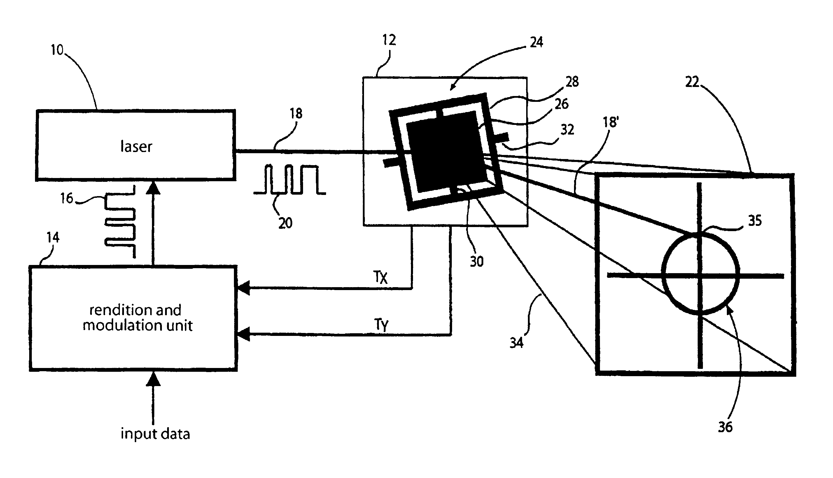
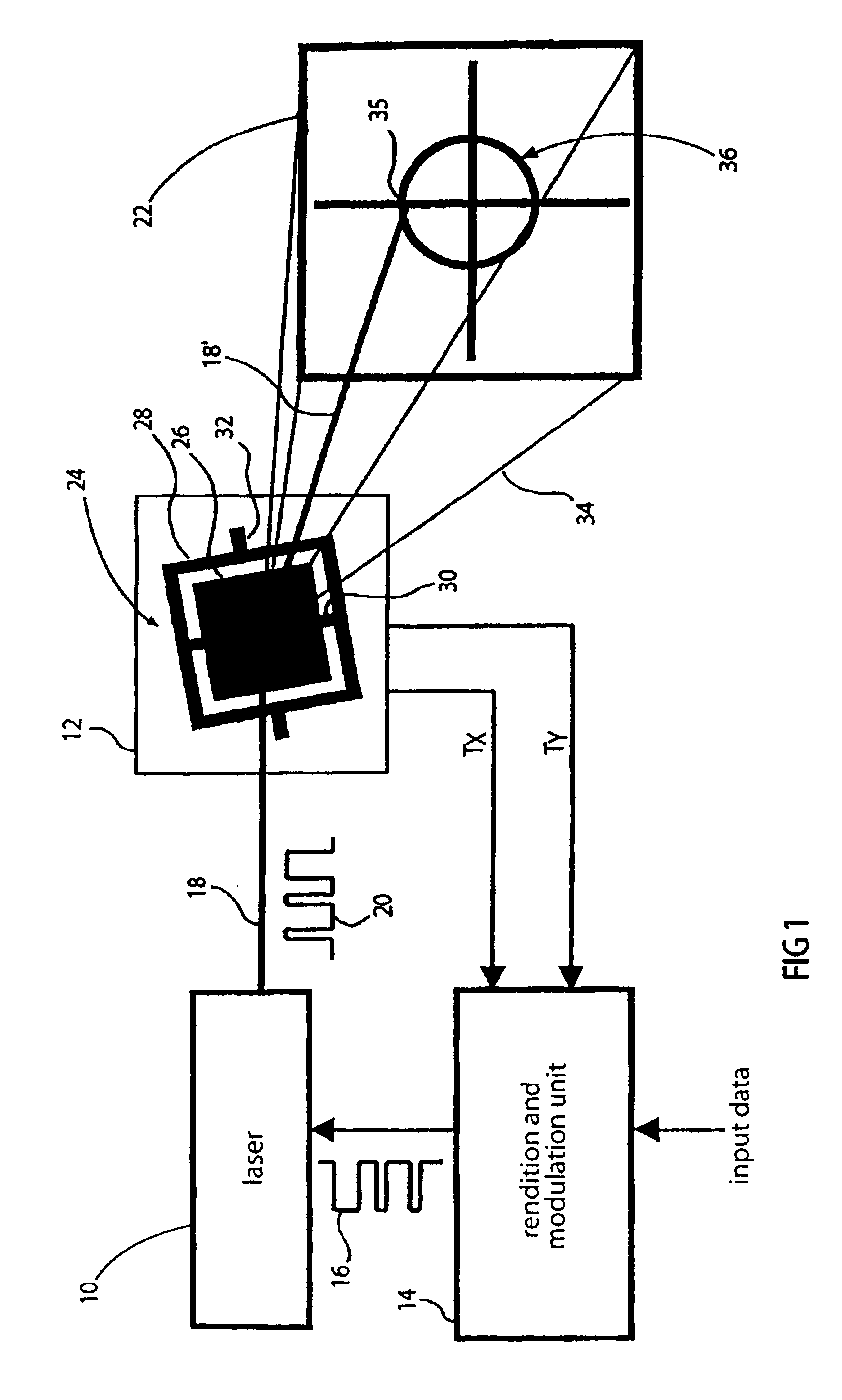
With reference to FIG. 1, the construction of a projection apparatus according to one embodiment of the present invention is described first. It is pointed out that for better understanding the illustration of FIG. 1 is not embodied to scale. Furthermore, FIG. 1 is related to the projection apparatus for the monochrome representation of an image, although the present invention is also applicable to projection apparatuses providing the colored representation of an image.

The projection apparatus of claim 1 includes a laser 10, a deflection means 12 and a rendition and modulation unit 14. The rendition and modulation unit 14 receives at an input input image data representing the image to be projected and is connected to a control input of the laser 10 via an output, in order to send the digital control signal 16 thereto, by which the intensity of a laser beam 18 sent out from the laser 10 is modulated, as it is schematically illustrated by an intensity profile 20 corresponding to the p...


PUM


Abstract

The present invention is based on the finding that the previous column and row representation in the scanning image projection has to be given up, in order to enable that the ratio between row and column frequency or vertical and horizontal deflection frequency is not critical and may be decreased. An inventive projection apparatus for projecting an image on an image field includes a deflection means for deflecting a light beam about a first deflection axis at a first deflection frequency and about a second deflection axis at a second deflection frequency different from the first, in order to move the light beam across the image field, as well as a modulation means for modulating an intensity of the light beam depending on the image to be projected. The first and second deflection frequencies differ by less than an order of magnitude.

Description

BACKGROUND OF THE INVENTION1. Field of the InventionThe present invention relates to projection apparatuses and in particular to miniaturized low-cost light projectors, as they are used for the representation of images, patterns, characters, or symbols or for the illumination of a photosensitive material.2. Description of the Related ArtFor the projection of images, either parallel methods, as it is the case for example with LCDs (liquid crystal displays) or with micro-mirror arrays, or scanning methods are used, as they are for example realized by a biaxially movable or two uniaxially movable mirrors. Disadvantageously, in the parallel methods, a comparably large substrate area in manufacturing and also a complex test procedure are required. Both result in a comparably high price for parallel-type projectors, so that methods working in parallel are not considered for a low-cost projection apparatus.In the scanning methods, the projectors include one or two movable mirrors enabling ...

Claims


Application Information

Patent Timeline
Patent Type & Authority Patents(United States)
IPC IPC(8): G02B26/10G02B27/18H04N5/74
CPCG02B26/105G02B27/18H04N5/7416G02B26/101
Inventor SCHENK, HARALDWOLTER, ALEXANDERSCHWARZENBERG, MARKUS
Owner FRAUNHOFER GESELLSCHAFT ZUR FOERDERUNG DER ANGEWANDTEN FORSCHUNG EV
Why Eureka
Try Eureka