
Cutting tool and indexiable insert therefor

a technology of indexing inserts and cutting tools, which is applied in the direction of cutting inserts, manufacturing tools, shaping cutters, etc., to achieve the effects of stable chip deformation effect, small cutting resistance and high rigidity

Inactive Publication Date: 2005-01-18
NGK SPARK PLUG CO LTD
View PDF14 Cites 23 Cited by
  • Summary
  • Abstract
  • Description
  • Claims
  • Application Information

AI Technical Summary

Benefits of technology

[0005]In cutting off of a work in the form of bar by using the related insert 101, the chip K is forcedly pressed against the projections 120, 120 adjacent the opposite ends of the cutting edge 115 and thereby deformed in cross section. By the projections 120, 120, a large cutting resistance is caused and applied to the insert 101 as compared with an insert that is not provided with such projections, thus causing the cutting edge to wear in a shorter period and therefore the life of the insert to become shorter.

Problems solved by technology

In addition, such a large cutting resistance causes the following problem in cutting off.
Accordingly, also in this instance, when the cut-off work is required to have a highly accurate machining of the end face, it is similarly and inevitably required to carry out an additional process for removing the burrs.

Method used


Image

  • Cutting tool and indexiable insert therefor
  • Cutting tool and indexiable insert therefor
  • Cutting tool and indexiable insert therefor

Examples


third embodiment

[0030]FIG. 9 is a perspective view of an important portion of an indexable insert according to the present invention;

[0031]FIG. 10 is an enlarged side elevational view of the important portion of the indexable insert of FIG. 9 when observed from a side flank side;

fourth embodiment

[0032]FIG. 11 is a perspective view of an important portion of an indexable insert according to the present invention;

[0033]FIG. 12 is a side elevational view of the important portion of the indexable insert of FIG. 12 when observed from a side flank side; and

[0034]FIG. 13 is a plan view of an important portion of a related indexable insert for cutting off.

DESCRIPTION OF THE PREFERRED EMBODIMENTS

first embodiment

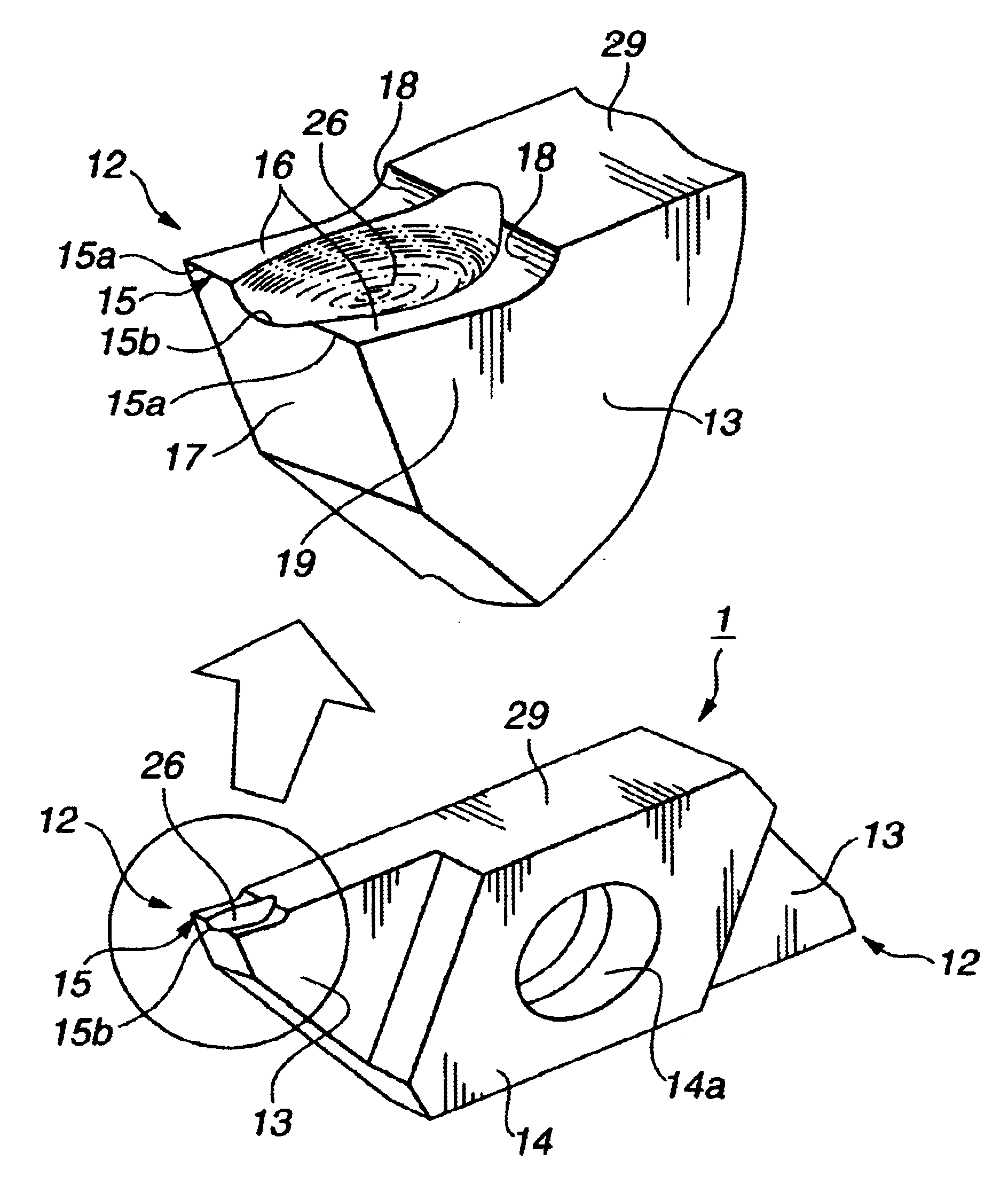
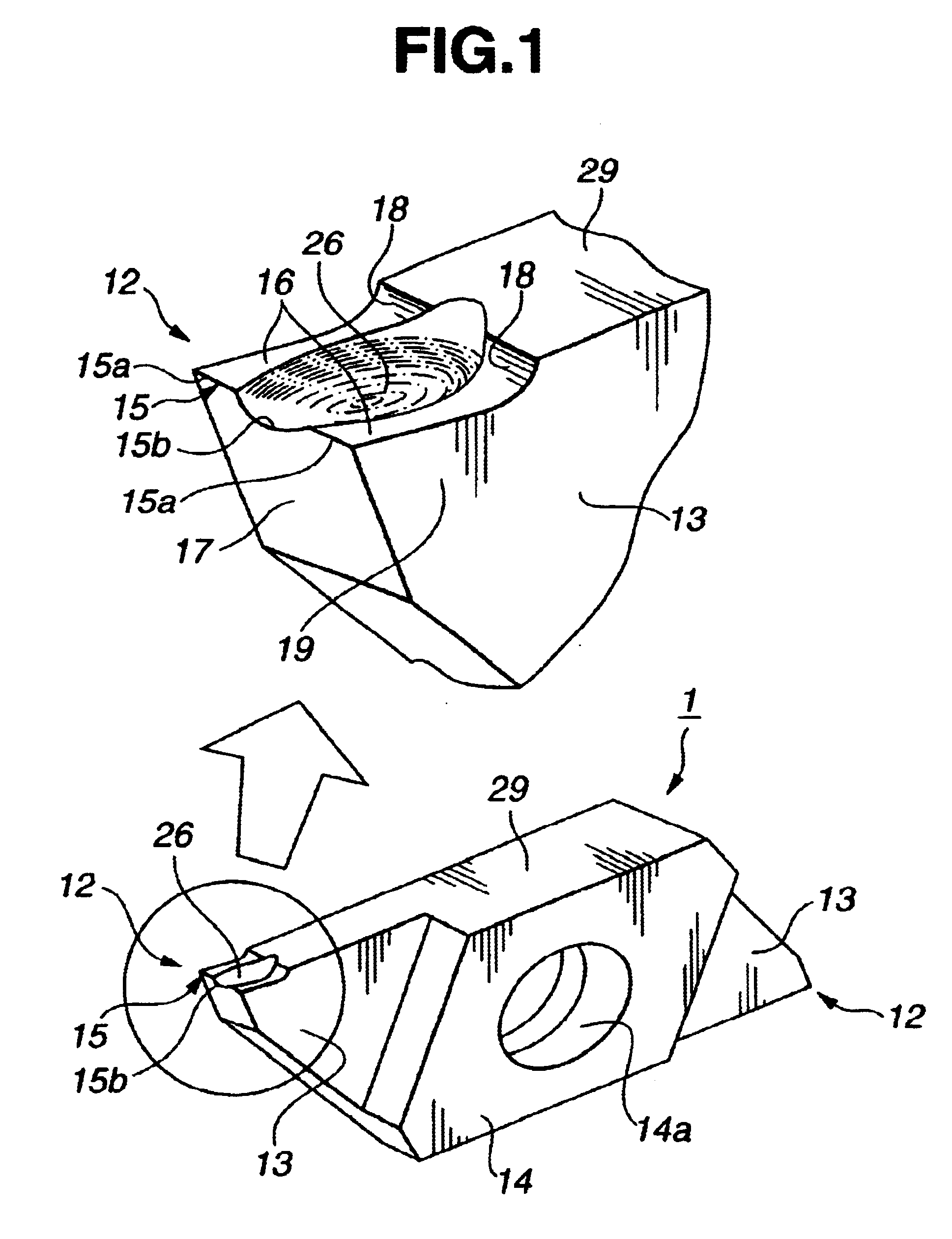
[0035]Referring first to FIGS. 1 to 5, inclusive, an indexable insert according to the present invention is generally designated by 1 and is made up of a sintered body of a super alloy, cermet or ceramic. The indexable insert 1 is in the form of a parallelogram block when observed in a side elevation thereof and of a two-corner type having a pair of sharp angled ends 12, 12 each of which has an end cutting edge 15. Thus, description is made with respect to a first corner. In this embodiment, triangular portions 13, 13 having the sharp angled ends 12, 12 are formed thinner, and a remaining thicker portion 14 has a central fixing hole 14a used for clamping the indexable insert 1 in a holder (not shown).

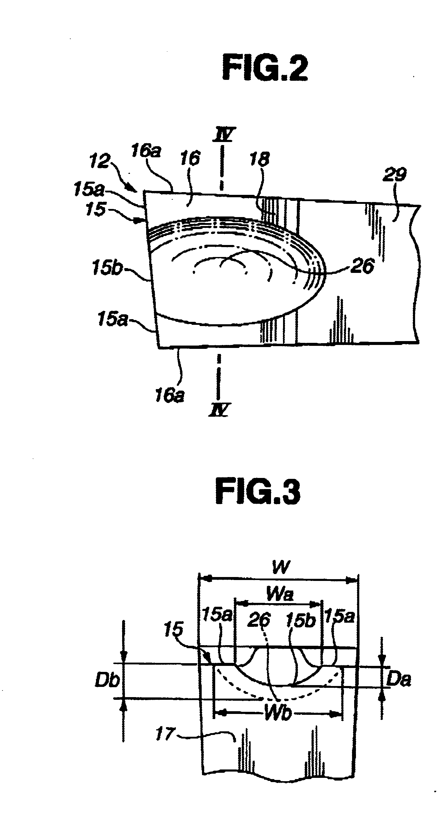
[0036]The end cutting edge 15 at the first corner is formed at a junction of a rake face 16 and a front end flank 17. The rake face 16, when observed from the above (i.e., when observed in plan), has a pair of opposite sides 16a, 16a extending straightly or linearly rearward from the op...


PUM

PropertyMeasurementUnit
depthaaaaaaaaaa
rake angleaaaaaaaaaa
side relief angleaaaaaaaaaa

Abstract

A cutting tool is provided which comprises an end cutting edge at an end of a rake face, and a depression formed in the rake face so as to provide the end cutting edge with a concave edge portion.

Description

BACKGROUND OF THE INVENTION[0002]The present invention relates to a cutting tool for cutting off and grooving by turning and an indexable insert (throwaway tip) for such a cutting tool.[0003]Shown in FIG. 13 is a related indexable insert 101 for a bit or cutting tool used for cutting off or grooving by turning. The insert 101 has a pair of projections (beveled walls) 120, 120 on a rake face 116. The projections 120, 120 are disposed adjacent an end cutting edge 115 and the opposite ends of the rake face 116. With such an insert 101, a chip K is forcedly pressed against the projections 120, 120 and deformed into a convexly or V-like bent cross section before being removed from the place where cutting is performed.[0004]The chip K deformed as above by such an insert 101 is higher in rigidity as compared with a chip of a flat cross section and can be easily divided into sections of suitable lengths even if it is removed so as to have a spiral shape. Thus, the chip does not coil around ...

Claims


Application Information

Patent Timeline
Patent Type & Authority Patents(United States)
IPC IPC(8): B23B27/04B23B27/00B23B27/02
CPCB23B27/045B23B2200/087Y10T407/235Y10T407/25Y10T407/2268B23B2200/202B23B27/02
Inventor INAYAMA, TAKASHI
Owner NGK SPARK PLUG CO LTD
Learn More