Electrical connector with voltage detection point insulation shield

Active Publication Date: 2005-01-18
THOMAS & BETTS INT INC
View PDF41 Cites 114 Cited by
  • Summary
  • Abstract
  • Description
  • Claims
  • Application Information

AI Technical Summary

Benefits of technology

It is a further object of the invention to provide an electrical cable connector with a plastic shell disposed on a voltage detection point interface surface thereof to reduce friction between the interface surface and a protective cap inserted thereon.
It is still a further object of the present inventi

Problems solved by technology

Service personnel commonly encounter difficulty in reliably determining whether or not a voltage is present on a loadbreak elbow.
Failure of the device could indicate a false voltage status which may lead service personnel to assume that there is no voltage on the conductor when a voltage is in fact present, which presents an obvious safety hazard.
Electrical shock hazards can also arise when the test point terminal and the area surrounding the terminal are not carefully manufactured or are subject to debris and contaminants.
For example, irregularities, voids and even mold parting lines formed in the surfaces surrounding the voltage test point terminal may increase the chances of an electrical short and/or failure.
Such irr

Method used


Image

  • Electrical connector with voltage detection point insulation shield
  • Electrical connector with voltage detection point insulation shield
  • Electrical connector with voltage detection point insulation shield

Examples


Example

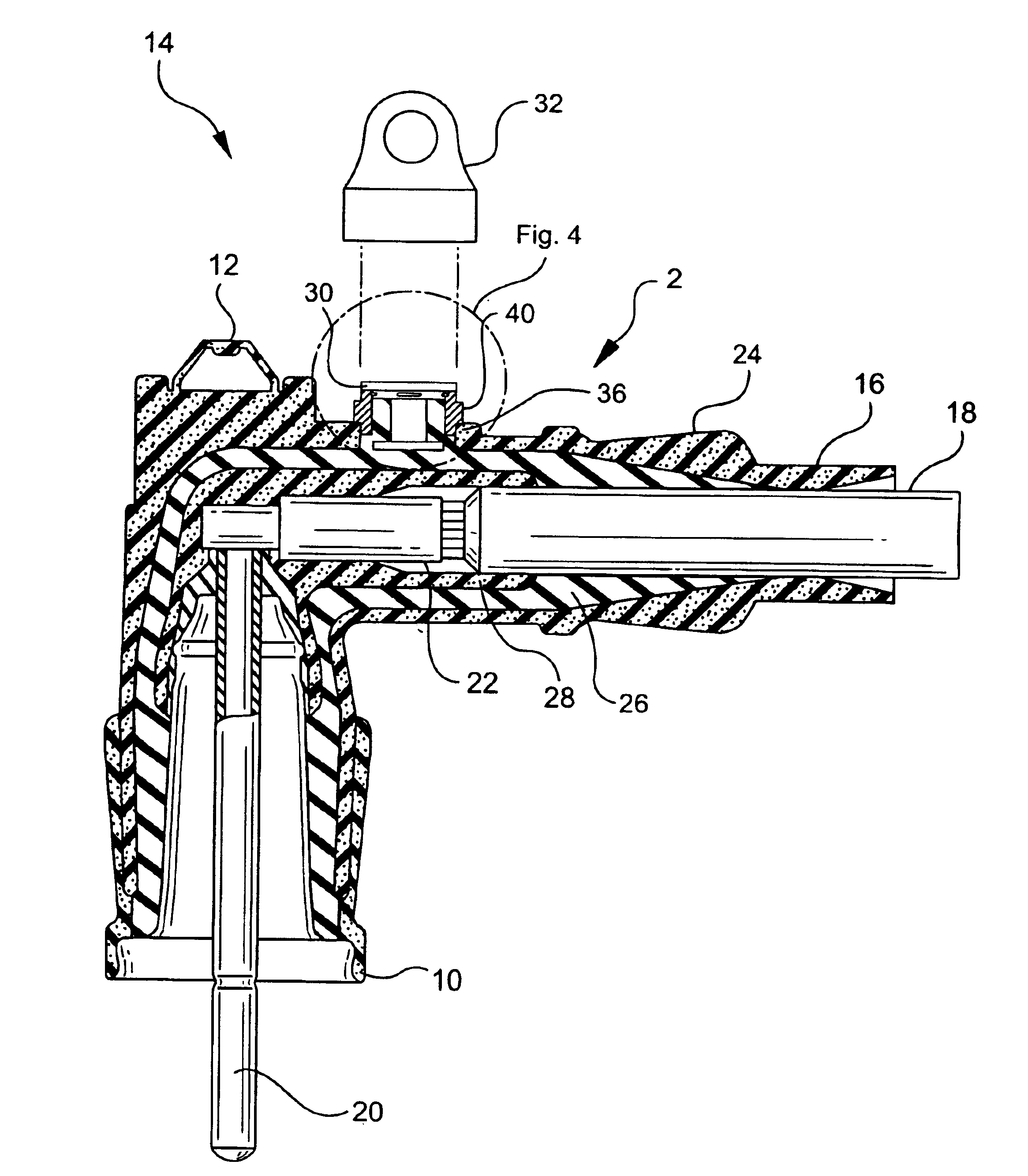
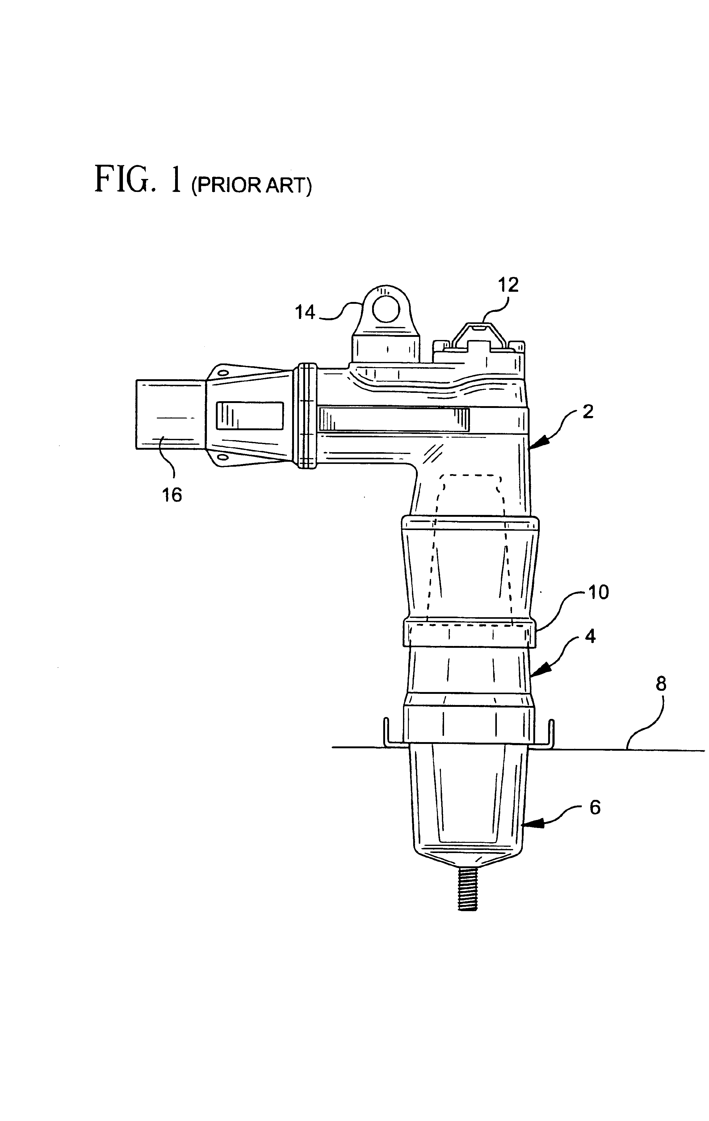
Referring first to FIGS. 1 and 2, prior art loadbreak connectors are illustrated. In FIG. 1, a power cable elbow connector 2 is illustrated coupled to a loadbreak bushing insert 4, which is seated in a universal bushing well 6. The bushing well 6 is seated on an apparatus face plate 8. The power cable elbow connector 2 includes a first end adapted for receiving a loadbreak bushing insert 4 and having a flange or elbow cuff 10 surrounding the open receiving end thereof. A power cable receiving end 16 is provided at the opposite end of the power cable elbow connector and a conductive member extends from the power cable receiving end to the bushing insert receiving end 10 for connection to a probe insertion end of the bushing insert.

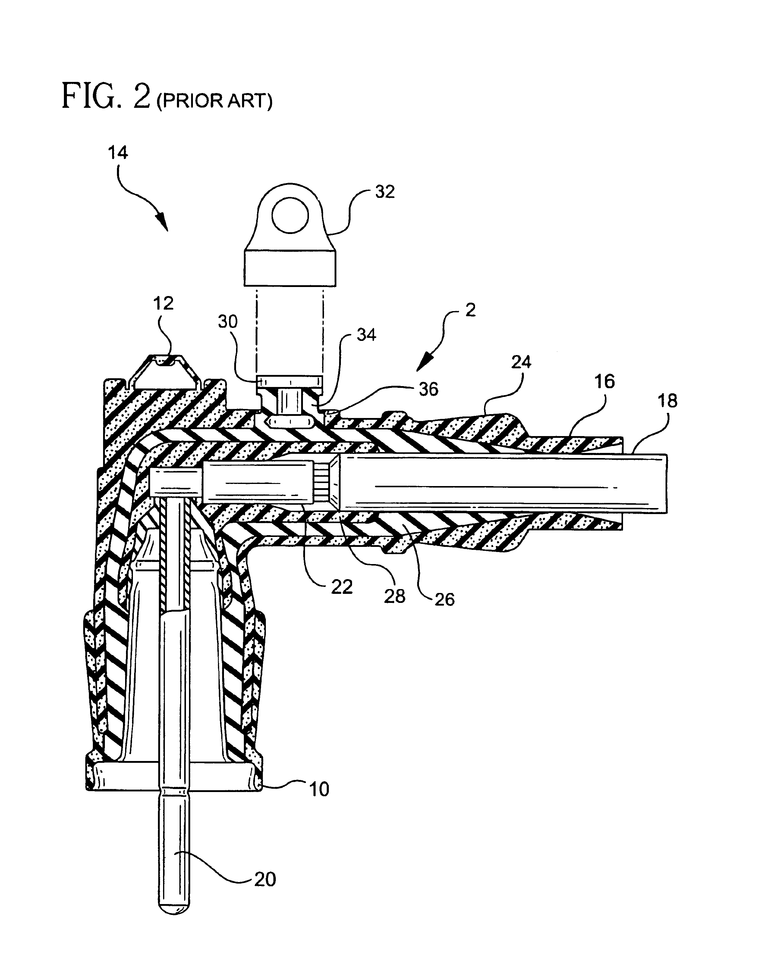
FIG. 2 is a cross-sectional view of a prior art power cable elbow connector 2, which includes a cable receiving end 16 having a cable 18 therein. The other end of the power cable elbow is a loadbreak bushing insert receiving end 10 having a probe or energiz...


PUM


Abstract

An electrical cable connector having a voltage detection test point generally includes an internal conductor, an inner insulating sheath surrounding the conductor, a conductive outer shield surrounding the insulating sheath, a separately molded plastic insulative shield disposed adjacent an opening formed in the conductive outer shield and held by the inner insulating sheath and a conductive voltage detection test point terminal disposed within the plastic insulative shield, wherein the test point terminal is capacitively coupled to the internal conductor for external testing of a voltage of the connector. In a preferred method for forming an electrical cable connector, such as a loadbreak power cable elbow connector, having a voltage detection test point, an insulative shield is first molded from a thermoplastic and a conductive voltage detection test point terminal is inserted within the plastic insulative shield. An outer shield is then molded from a conductive material. The conductive outer shield has an opening formed therethrough for accommodating the pre-assembled insulative plastic shield and test point terminal. After the pre-assembled insulative plastic shield and test point terminal are positioned adjacent the opening of the conductive outer shield, and after the conductive outer shield and an internal conductor are positioned within a mold cavity, an inner insulative housing is molded within the conductive outer shield and around the internal conductor. Upon molding, the pre-assembled insulative plastic shield and the test point terminal is held to the inner insulative housing. As a result, the test point terminal becomes capacitively coupled to the internal conductor for external testing of a voltage of the connector.

Description

BACKGROUND OF THE INVENTION1. Field of the InventionThe present invention relates to electrical cable connectors, such as loadbreak connectors and deadbreak connectors, and more particularly to an electrical cable connector, such as a power cable elbow connector, having a voltage detection point insulation shield, which is provided during a molding process to preserve the critical electrical interfaces of the connector.2. Description of the Prior ArtLoadbreak cable connectors used in conjunction with 15, 25 and 35 kV switchgears generally include a power cable elbow connector having one end adapted for receiving a power cable and another end adapted for receiving a loadbreak bushing insert. The end adapted for receiving the bushing insert generally includes an elbow cuff for providing an interference fit with a molded flange on the bushing insert. This interference fit between the elbow cuff and the bushing insert provides a moisture and dust seal therebetween. An indicator band may...

Claims


Application Information

Patent Timeline
IPC IPC(8): H01R13/53H01R11/22H01R11/11H01R4/22H01R4/00
CPCH01R13/53H01R4/22H01R11/22Y10S439/921H01R2201/20Y10S439/912G01R15/16
Inventor BORGSTROM, ALANKNIGHT, JOHN
Owner THOMAS & BETTS INT INC
Why Eureka
Try Eureka