Folder cylinder with support plate

Inactive Publication Date: 2005-01-18
SHANGHAI ELECTRICGROUP CORP
View PDF9 Cites 12 Cited by
  • Summary
  • Abstract
  • Description
  • Claims
  • Application Information

AI Technical Summary

Benefits of technology

An object of the present invention is to provide a folding cylinder with improved support for signatures. An additi

Problems solved by technology

If large cross-fold adjustment is desired, the gaps in the transfer cylinder must be rather large, which can lead to a lack of support for signatures that in turn can lead to

Method used


Image

  • Folder cylinder with support plate
  • Folder cylinder with support plate
  • Folder cylinder with support plate

Examples


Example

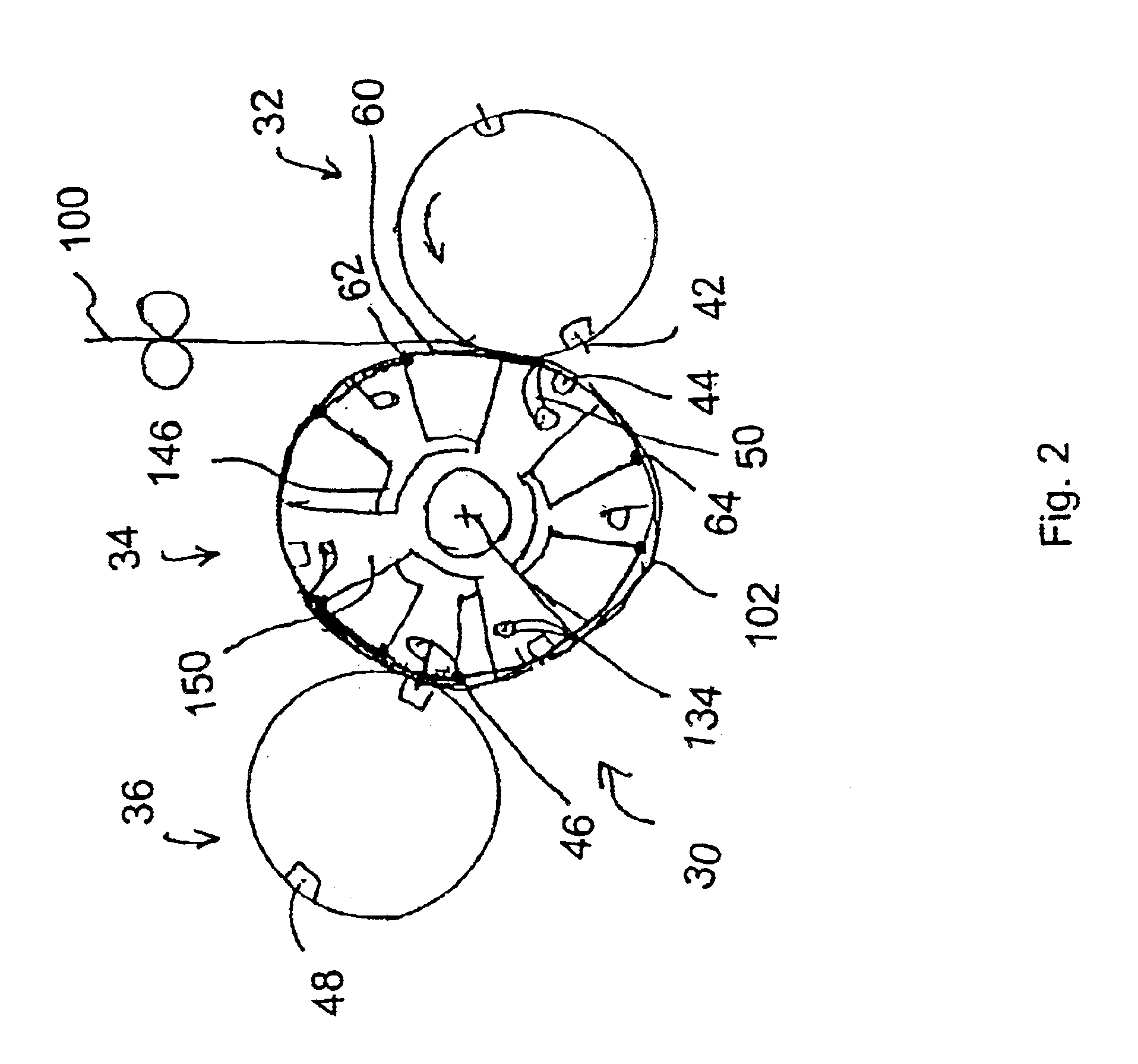
FIG. 2 shows a schematic side view of a jaw folder 30 having a cutting cylinder 32, a transfer cylinder 34 and a jaw cylinder 36. Web 100 is cut by the cutting cylinder 32, which has knives 42 acting against anvils 44 on the transfer cylinder 34, so that signatures 102 are formed. Pins 50 hold the lead edge of signatures 102 in place. Signatures 102 are tucking into jaws 48 of jaw cylinder 36 by tuckers 46 of transfer cylinder 34. Transfer cylinder 34 has a central axis 134. Tucker spider 146 supports tuckers 46 and gripper spider 150 supports pins 50 and anvils 44.

Covers 60 extend over the pins 50, and are fastened by a fastener 62, for example screws, at one end to one arm of tucker spider 146 and at the other end by a fastener 64. The covers 60 have apertures through which the pins 50 can extend. While covers 60 are fixed to spider 146, spider 150 can rotate with respect to covers 60, and thus the apertures preferably are elongated in the circumferential direction so that the pin...


PUM

PropertyMeasurementUnit
Folded conformationaaaaaaaaaa

Abstract

A folding cylinder includes a plurality of gripping devices supported on a first rotatable support with a first gripping device for holding a signature on the cylinder. A plurality of tucking devices are supported on a second rotatable support, the tucking devices including a first tucking device and a second tucking device. The first gripping device is located circumferentially between the first tucking device and second tucking device and a cover fixed to the second rotatable support extends circumferentially over the first gripping device between the first tucking device and the second tucking device. The cover has at least one aperture, with the first gripping device capable of extending through the at least one aperture. With the folding cylinder of the invention gaps between the tucking and gripping spiders can be eliminated.

Description

BACKGROUND OF THE INVENTIONThe present invention relates generally to printing presses and more particularly to a folder of a printing press.Web printing press print a continuous web of material, such as paper. In a folder of the web printing press, the continuous web then is cut into signatures in a cutting unit and folded.U.S. Pat. No. 5,429,578 describes a jaw folder receiving a web of material. A cutting cylinder, transfer cylinder and jaw cylinder are provided. The web is cut by the transfer cylinder where the lead edge of the signature is secured by pins. The signature is thus held on the transfer cylinder until tucking blades on the transfer cylinder tuck the signatures into jaws of the jaw cylinder. Thus a cross-fold on the signatures is created along a fold line perpendicular to the travel direction of the signatures. The signatures are then held by the jaws at the fold line until the signatures are to be released. In order to change the position of the fold with respect to...

Claims


Application Information

Patent Timeline
IPC IPC(8): B41F13/54B41F13/62B65H45/16B31F1/08B65H45/28
CPCB65H45/166B41F13/62
Inventor JACKSON, BARRY MARKPOLLOCK, DAVID CLARKE
Owner SHANGHAI ELECTRICGROUP CORP
Why Eureka
Try Eureka