High efficiency magnetic sensor for magnetic particles

a magnetic sensor and high-efficiency technology, applied in the field of sensing devices, can solve the problem that the recognition events of binding assays cannot be observed directly, and achieve the effect of maximizing the ability of a magnetic sensing elemen

Inactive Publication Date: 2005-01-18
THE UNITED STATES OF AMERICA AS REPRESENTED BY THE SECRETARY OF THE NAVY
View PDF2 Cites 40 Cited by
  • Summary
  • Abstract
  • Description
  • Claims
  • Application Information

AI Technical Summary

Benefits of technology

Accordingly, it is an object of this invention to maximize the ability of a magnetic sensing element to detect an attached magnetic particle.

Problems solved by technology

Typically, because of the small size of the molecules involved, recognition events in a binding assay cannot be observed directly.

Method used


Image

  • High efficiency magnetic sensor for magnetic particles
  • High efficiency magnetic sensor for magnetic particles
  • High efficiency magnetic sensor for magnetic particles

Examples


second embodiment

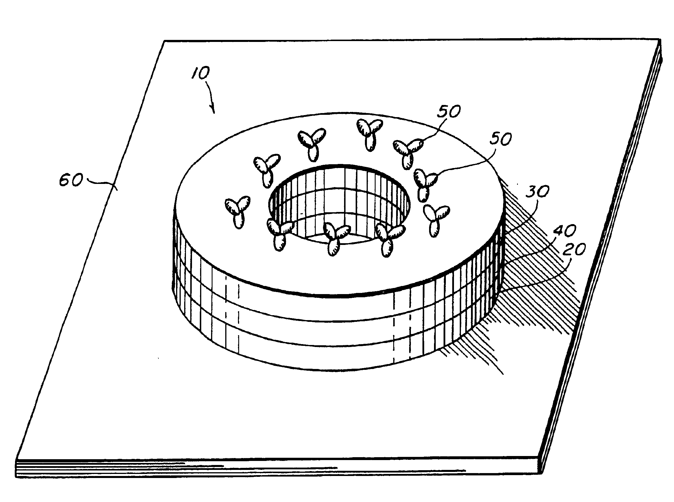
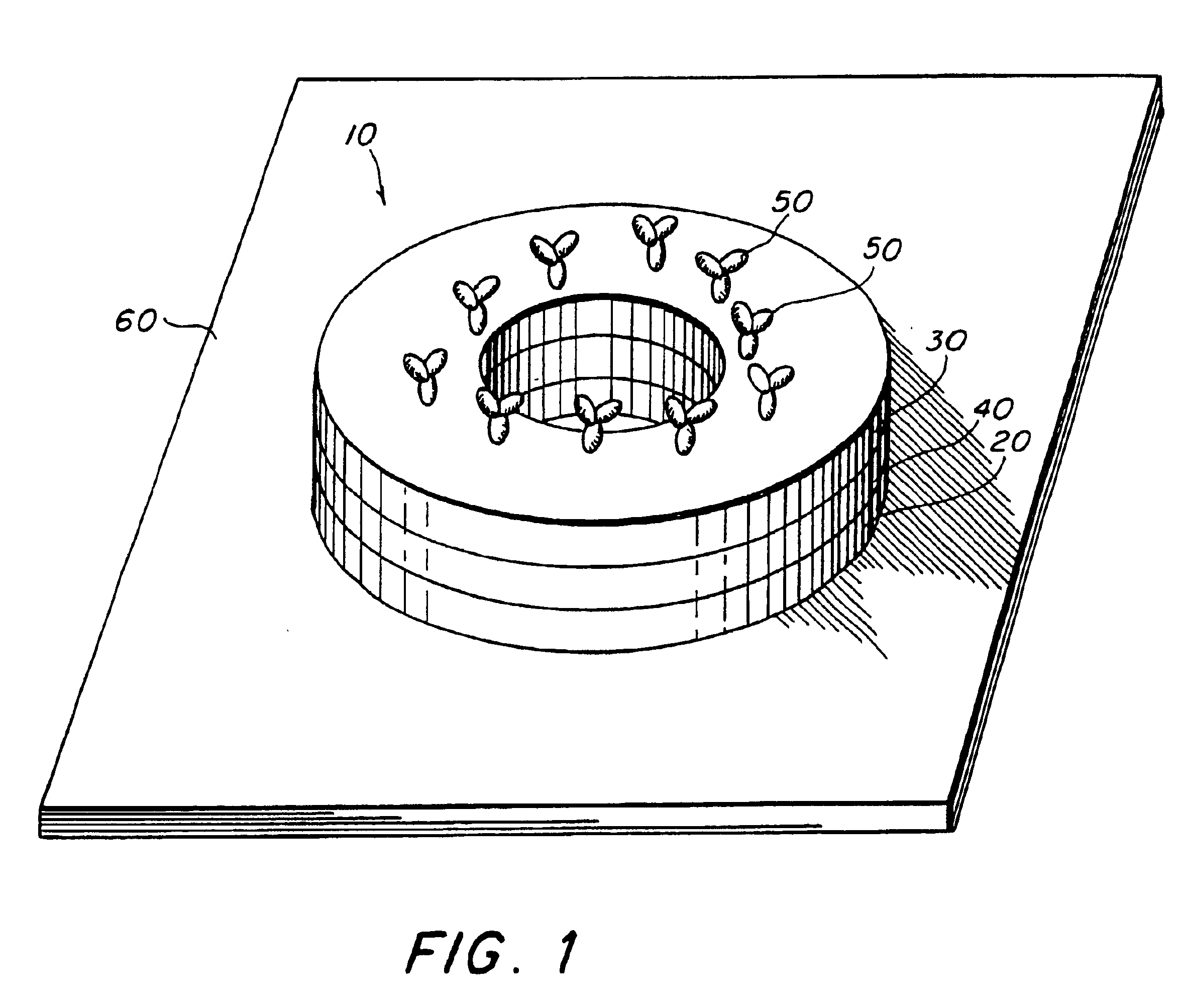
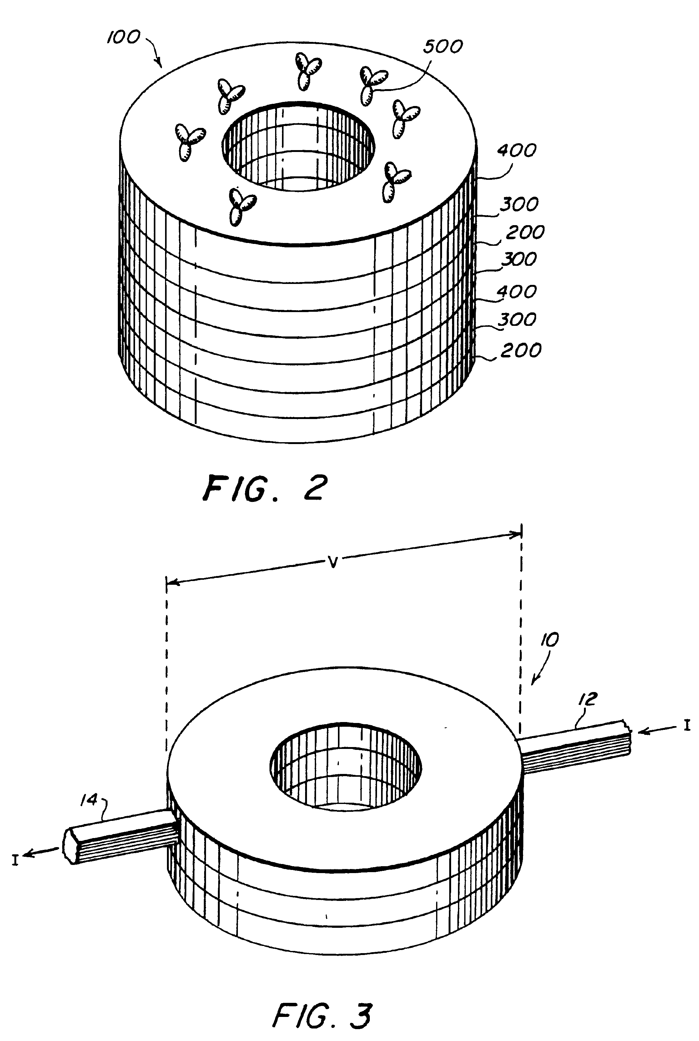
The second embodiment, also a giant magnetoresistive (GMR) device, uses the above-described structure with the additional effect described Prinz '868 in which an electrical current passing through the ring stack causes the soft layer magnetization to reverse. The radial magnetic field of the magnetic particle coupled with this current induced reversal allows for a threshold to be set by either the current or the particle field and for the threshold to be crossed by either the particle field or the current. The effect of the magnetic field from the particle is to rotate the soft layer moment to a radial orientation. A current sent through either the ring, a coaxial current lead (see above) or combination thereof will then counter-rotate the moments in the soft layer(s) relative to the original orientation. With a bead present providing an additional “boost”, the element is then made to “latch” in a high or low state. This embodiment can also have either a current-in-plane (CIP) confi...

fifth embodiment

A fifth embodiment, also a magnetic tunnel junction (MTJ) device like the fourth embodiment, uses an electrical current as in the second embodiment to “latch” the device. In principle, a “switching” current could be sent down the ring to counterrotate the magnetization of the layers. Practically speaking, the large currents necessary for this would probably damage the tunnel junction. More preferable would be to use a coaxial auxiliary current lead for this purpose.

A sixth embodiment, an anisotropic magnetoresistive (AMR) device, includes one or more ferromagnetic layers and current leads that direct current through the sensing element in a circumferential current-in-plane (CCP) orientation. With no perturbing field from a magnetic particle, the magnetization of the ferromagnetic layers is either parallel or antiparallel to the current. The radial component of the fringing field of a magnetic particle causes the moments of the ferromagnetic layers to align radially and become perpen...


PUM

PropertyMeasurementUnit
magneticaaaaaaaaaa
circular magnetic momentaaaaaaaaaa
magnetic momentaaaaaaaaaa

Abstract

A magnetic sensing element detects the presence of magnetic particles in a binding assay. The magnetic sensing element has at least one planar layer of electrically conductive ferromagnetic material that has an initial state in which the material has a circular magnetic moment within the plane of the layer. The magnetic sensing element has molecules of a first specific binding member attached to it. The device also includes a fluid test medium to which the magnetic sensing element is exposed during the course of a binding assay. The fluid test medium includes magnetizable particles that become immobilized during the assay in relation to the amount of analyte in the test medium. The relative size of the magnetic particle and the magnetic sensing element and the location of the molecules of the first specific binding member on the magnetic sensing element are selected so that when the magnetic particle becomes immobilized with respect to the magnetic sensing element, the radial fringing field of the magnetic particle causes the magnetic moment of at least one layer of electrically conductive ferromagnetic material to shift from circular to radial, thereby causing a detectable change in the electrical resistance of the magnetic sensing element.

Description

BACKGROUND OF THE INVENTION1. Field of the InventionThe present invention relates generally to a sensing device for use in a binding assay for detecting the presence of an analyte and more particularly to a sensing device having a magnetic sensing element that responds to the radial fringing field of a magnetic particle.2. Description of the Background ArtBinding assays such as immunoassays, DNA hybridization assays, and receptor-based assays are widely used in the medical community as diagnostic tests for a wide range of target molecules or analytes. Binding assays exploit the ability of certain molecules, herein referred to as “specific binding members”, to specifically bind target molecules. Specific binding members such as antibodies, strands of polynucleic acids (DNA or RNA) and molecular receptors, are capable of selectively binding to (“recognizing”) potential target molecules such as polynucleic acids, enzymes and other proteins, polymers, metal ions, and low molecular weigh...

Claims


Application Information

Patent Timeline
Patent Type & Authority Patents(United States)
IPC IPC(8): G01N27/72G01N15/10G01N33/543G01R33/06G01R33/09G11C11/15G11C11/02G01N33/58
CPCG01N27/745G11C11/15G01N33/54326G01N27/76
Inventor PRINZ, GARY A.MILLER, MICHAEL M.
Owner THE UNITED STATES OF AMERICA AS REPRESENTED BY THE SECRETARY OF THE NAVY
Why Eureka
Try Eureka