Compact stud finder

a compact, finder technology, applied in the field of electronic instruments, can solve the problems of inability to visually detect the location of the hidden substructure (i.e. the studs), the inability to find the presence of alternating current in the wall, and the cost of mass production, etc., to achieve the effect of efficient finding the location

Inactive Publication Date: 2005-01-18
ACTUANT CORP
View PDF25 Cites 134 Cited by
  • Summary
  • Abstract
  • Description
  • Claims
  • Application Information

AI Technical Summary

Benefits of technology

The invention provides a compact device capable of efficiently finding the location of hidden objects or substrata such as studs, joists and other similar objects below the surface of walls, floors and s...

Problems solved by technology

Carpenters, electricians, do-it-yourselfers and others are often faced with the problem of locating the position of the wall studs behind the wall board material forming the wall surface.
However after the walls are finished and painted the location of the hidden substructure (i.e. the studs) is not visually detectable.
Each individual circuit must be calibrated at the time of manufacture, which is a costly procedure for mass production.
Finding the presence of alternating current in walls is often not practical ...

Method used


Image

  • Compact stud finder
  • Compact stud finder
  • Compact stud finder

Examples


second embodiment

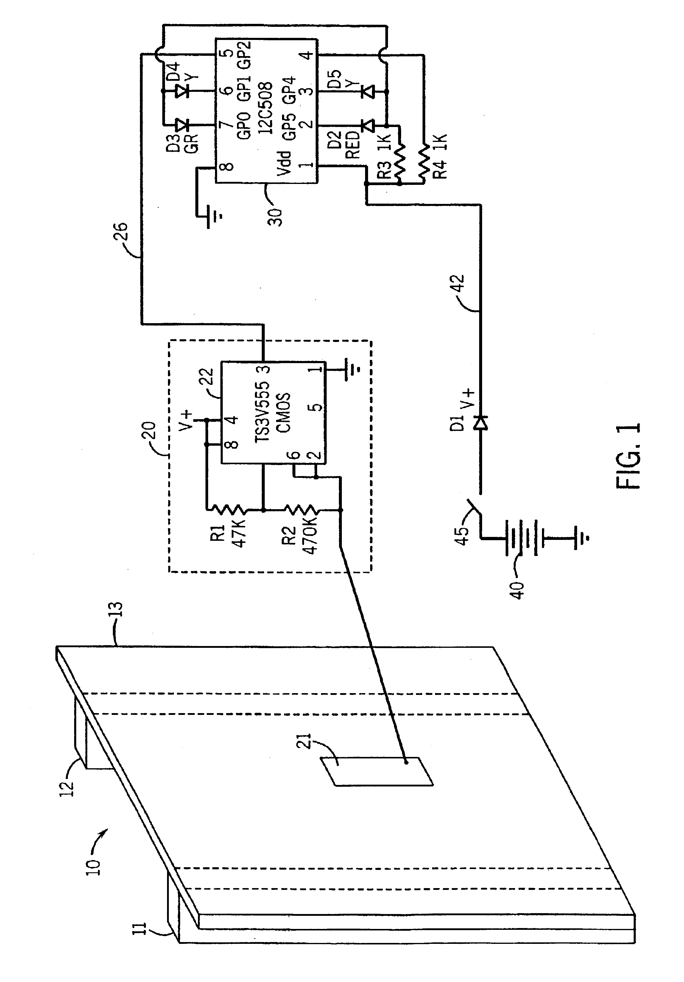
Referring to FIG. 3, there is illustrated a circuit diagram of the invention. Shown on this figure is a portion of a wall structure 60, studs 61, 62 and wall board 63 to be illustrative of one way of operating the invention. In this case, it is desired to locate the positions of the hidden studs 61 and 62. As shown in FIG. 3, there is a metallic sensor plate 71 connected to a CMOS oscillator 70. The frequency of the oscillator 70 is determined by IC 72, the values of resistors R1 and R2 and the capacitance presented by the plate 71.

The capacitance of the plate 71 is determined by the surrounding medium including the wall material, the studs, the circuit and the person holding the device. It is desirable to reduce the stray capacitance as much as possible since this will improve the sensitivity of the plate 71. The capacitance of plate 71 is influenced considerably by the operator and the housing of the device.

Capacitance is related to its potential with respect to other objects. If ...

first embodiment

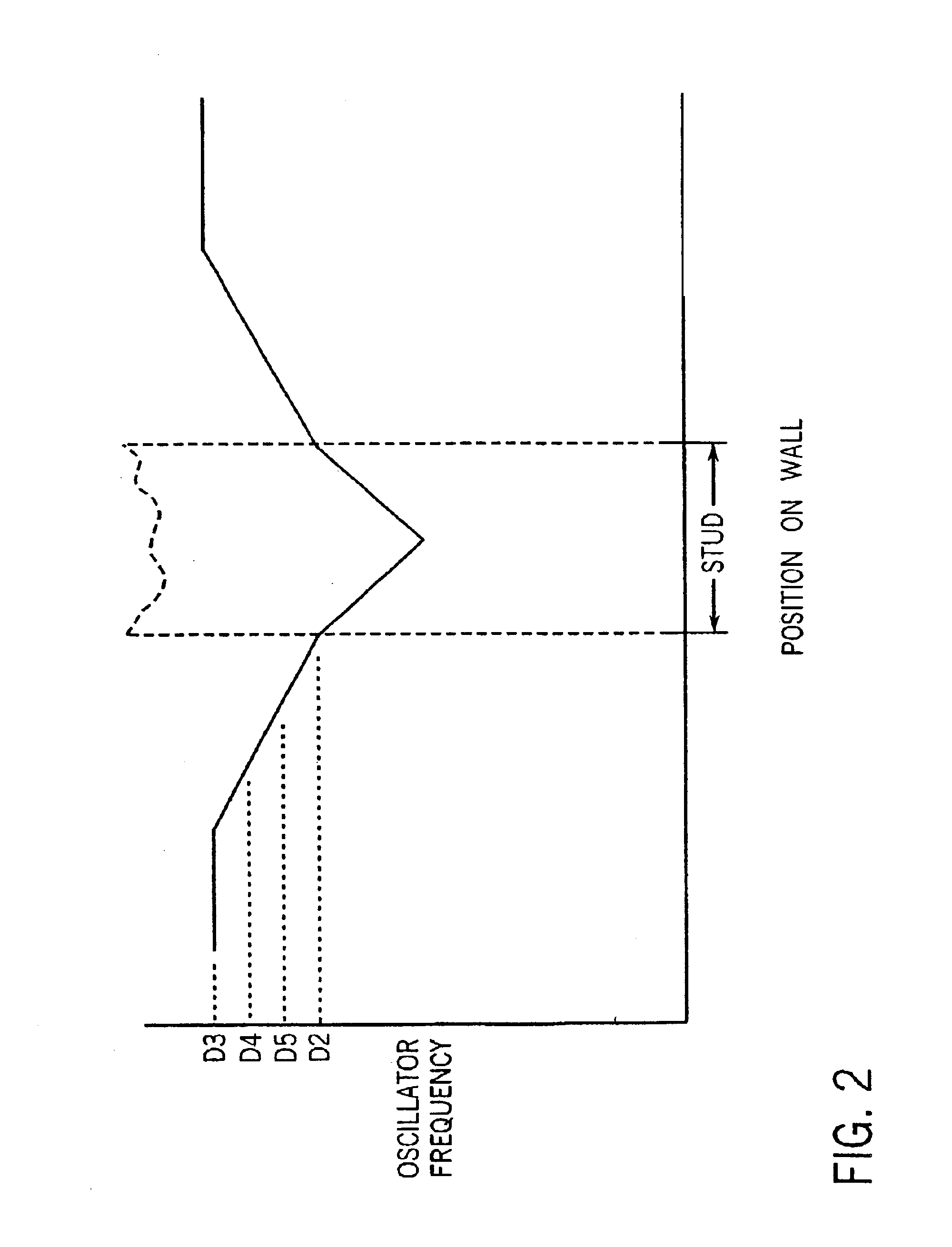
Referring back to FIG. 3, the remainder of the circuit of FIG. 3 acts in the same way as FIG. 1. When the sensor plate is above a section of the wall 63 with no studs it will cause the oscillator 70 to run at frequency f1. When the sensor is above a section of the wall 63 that has a stud below it the oscillator will have a different frequency f2. The output of the oscillator 70 goes to a microprocessor circuit 80 via line 76.

The microprocessor circuit 80 is programmed to measure the frequency difference f1 minus f2. As in the first embodiment, this can be done by any suitable means. For example, the microprocessor circuit 80 will typically include a counter. The counter can be programmed to count the number of times the oscillator output signal to the microprocessor goes high in a certain period, which yields a measure of the frequency of the oscillator output. If the frequency difference between the first measured frequency and the subsequently measured frequencies exceeds an amoun...


PUM


Abstract

A pocket-sized object finder has a compact housing containing a battery, circuitry and a capacitor plate for detecting an object hidden behind a wall. The battery powered circuitry includes multiple signal indicators that illuminate in a serial manner when the object is being detected. The signal indicators are successively tapered and are mounted at a front side of a tapered end of the housing. The capacitor plate is disposed in the housing along its rear wall and is responsive to variations in capacitance that occur as the object finder is brought near and over the object. The compact housing defines a cavity with a width that is no more than two inches and one third its length. A removable access door, with a pocket clip, at an end opposite the signal indicators allows access to the battery within the housing cavity.

Description

FIELD OF THE INVENTIONThis invention relates to electronic instruments for detecting a stud or other object behind an opaque surface, such as wall board.BACKGROUND OF THE INVENTIONCarpenters, electricians, do-it-yourselfers and others are often faced with the problem of locating the position of the wall studs behind the wall board material forming the wall surface. They are interested in hanging pictures, drilling holes and so on. However after the walls are finished and painted the location of the hidden substructure (i.e. the studs) is not visually detectable. The same is true of finding the location of hidden wooden frames in furniture and boats from the outside surface of the structure.U.S. Pat. No. 4,099,118 issued Jul. 4, 1978 discloses an electronic wall stud sensor which is suitable for detecting a wall stud behind a wall surface. It utilizes one or more capacitor plates, a fixed frequency oscillator, a dual one-shot multivibrator, a field effect transistor, and a complicate...

Claims


Application Information

Patent Timeline
IPC IPC(8): G01N27/22G01N27/24G01V3/15
CPCG01V3/15G01N27/24
Inventor STEBER, GEORGE R.LUEBKE, THOMAS M.SKEELS, STEPHEN J.WIESEMANN, DAVID L.
Owner ACTUANT CORP
Why Eureka
Try Eureka