
Method and apparatus of reducing ringing in a nuclear magnetic resonance probe

a nuclear magnetic resonance and probe technology, applied in the field of nmr well logging apparatus, can solve the problems of low saturation flux density, no provision, and core saturation, and achieve low magnetostriction, high internal damping, and high internal damping

Inactive Publication Date: 2005-01-18
BAKER HUGHES HLDG LLC
View PDF23 Cites 7 Cited by
  • Summary
  • Abstract
  • Description
  • Claims
  • Application Information

AI Technical Summary

Benefits of technology

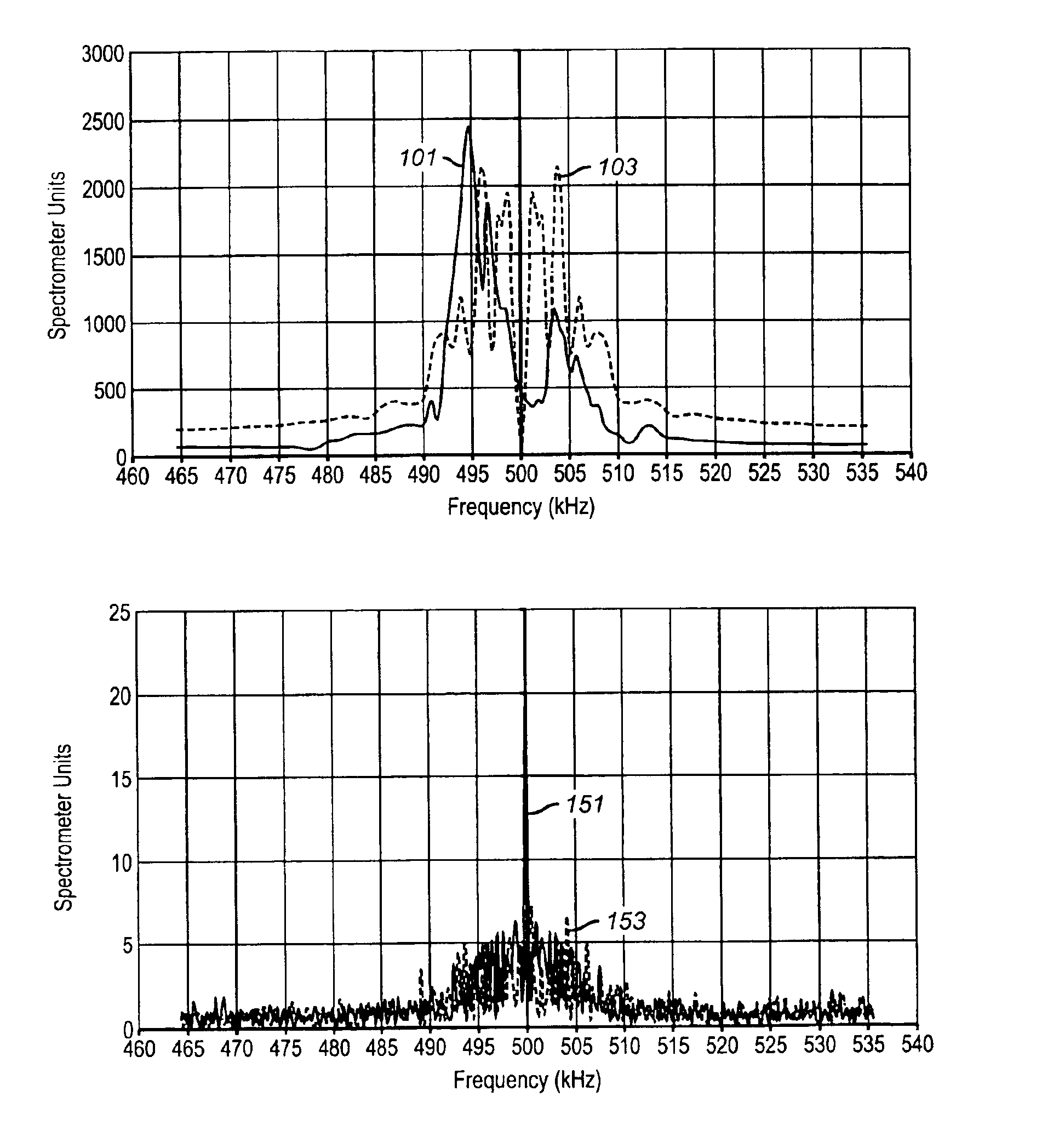
This solution enhances RF antenna efficiency by a factor of three, reduces sensitivity to temperature variations, and eliminates magnetostrictive ringing, enabling the use of more powerful magnets and increasing the signal-to-noise ratio while maintaining core stability.

Problems solved by technology

No provision was made in these early designs for the use of a soft magnetic material in the NMR probe for improving the efficiency of the RF antenna.
Ferrite materials, however, suffer from a relatively low saturation flux density, typically in the range of 0.3-0.4 T. This relatively low saturation flux density results in core saturation when the ferrite core is placed near the NMR probe permanent magnet.
Elimination of this parasitic magnetostrictive ringing signal increases the complexity and cost of NMR antenna design.
A common limitation of the '231, '566, '884, and '236 patent designs is the necessity of finding or creating a magnetic field low enough in a region where the soft ferrite material can be positioned to avoid saturation.
The necessity of creating a region of low static magnetic field places a serious constraint on the design of NMR probes.
In particular it places limitations on the antenna core size, thereby reducing the efficiency of the antenna.
The arrangement taught by Prammer has increased complexity and an increase of flux density and an accompanying risk of saturation in the ferrite layers.
While such a design is practical for wireline logging, it is difficult to do this with MWD logging tools.
However, the principles to be used in selecting suitable antenna core material for NMR applications were not fully explored therein.

Method used


Image

  • Method and apparatus of reducing ringing in a nuclear magnetic resonance probe
  • Method and apparatus of reducing ringing in a nuclear magnetic resonance probe
  • Method and apparatus of reducing ringing in a nuclear magnetic resonance probe

Examples


Embodiment Construction

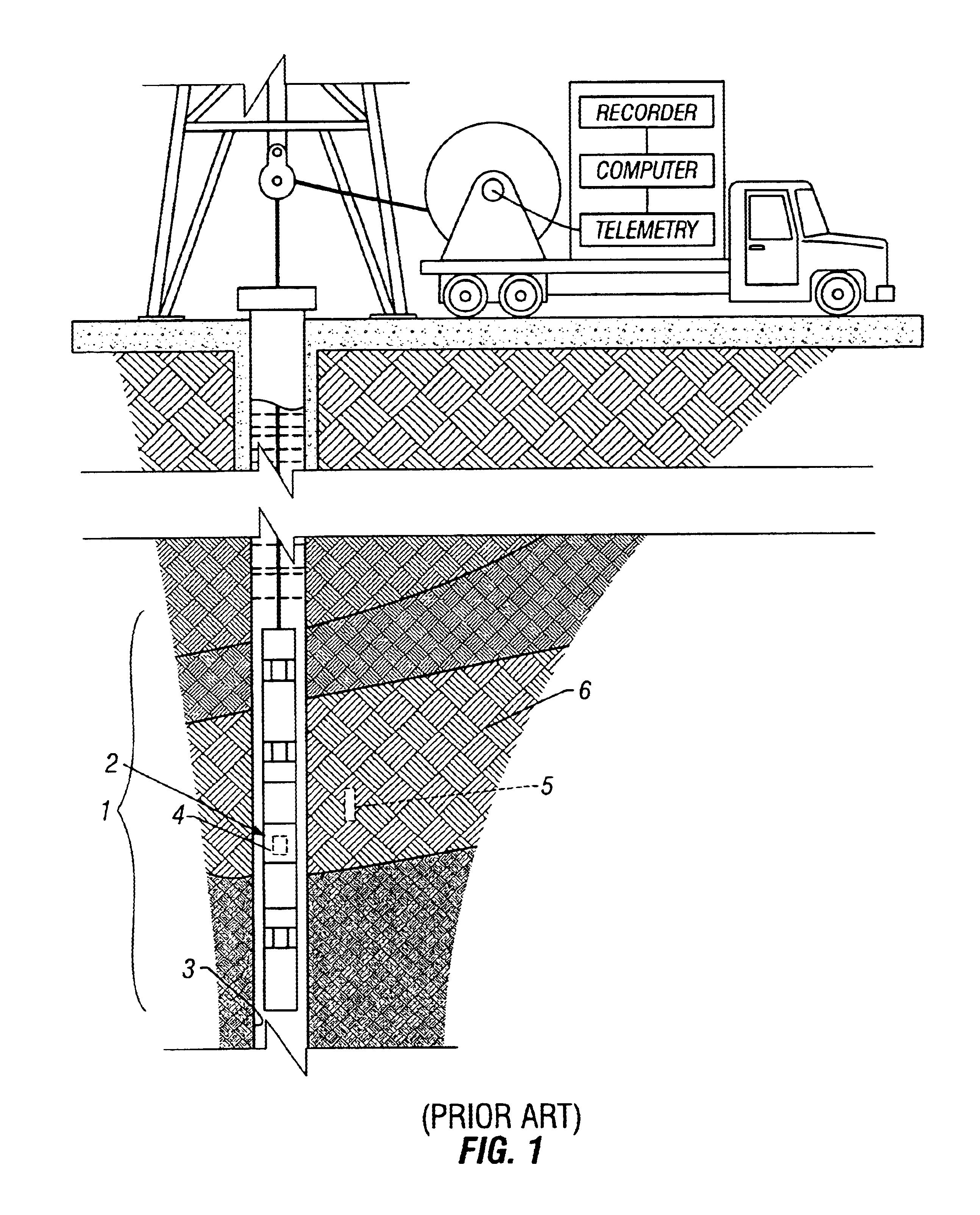
FIG. 1, illustrates well logging tool string 1 having an NMR probe 2, having antenna assembly 4 deployed in bore hole 3. The NMR probe sends magnetic pulses into and receives signals from region of investigation 5 in formation 6. FIG. 1 is shown for purposes of showing an example of the orientation of a tool utilizing the present invention and is not intended to limit the use of the present invention to a particular application or orientation.

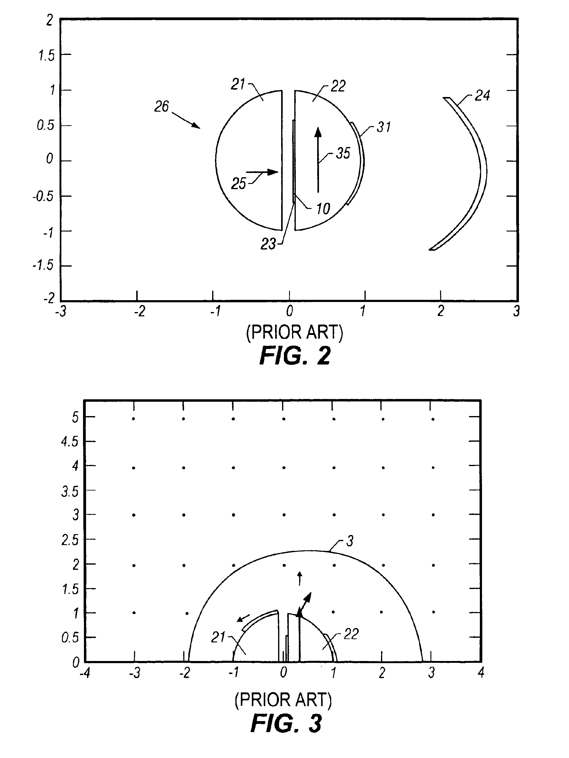
FIG. 2 illustrates a cross section of an exemplary logging tool for use with the present invention, taken perpendicular to axis of elongation. The preferred embodiment of FIG. 2, comprises a probe 2, moveable through a bore hole 3 for measuring nuclear magnetic resonance (NMR) properties of a formation 6 surrounding the bore hole. The preferred probe comprises an elongated permanent magnet 21, having an axis of elongation extending parallel to the axis of elongation of the probe 2 and parallel to the longitudinal axis of the bore hole 3. The ax...


PUM


Abstract

The present invention provides a novel use of a material having a high internal magnetostrictive damping and / or using material with explicitly low magnetostriction as a NMR probe core material. The probe structural geometry facilitates the use of material, which has a relatively low magnetic permeability.

Description

FIELD OF THE INVENTIONThe present invention is related to the field of nuclear magnetic resonance (“NMR”) sensing apparatus. More specifically, the invention is related to a NMR well logging apparatus having a powdered soft magnetic material core as a flux concentrator for sensing NMR properties within earth formations adjacent a wellbore.DESCRIPTION OF THE RELATED ARTNMR well logging instruments can be utilized for determining properties of earth formations including: the fractional volume of pore space, the fractional volume of mobile fluid filling the pore space and other petrophysical parameters. An NMR well logging instrument typically contains a permanent magnet to generate a static magnetic field in adjacent earth formations. The NMR well logging instrument typically includes a transmitting antenna assembly positioned near the magnet. The transmitting antenna assembly is shaped so that a pulse of radio frequency (RF) power conducted through the antenna assembly induces a RF m...

Claims


Application Information

Patent Timeline
Patent Type & Authority Patents(United States)
IPC IPC(8): G01V3/32G01R33/44G01V3/18G01R33/34
CPCG01N24/081G01V3/32G01R33/34
Inventor KRUSPE, THOMASREIDERMAN, ARCADYBLANZ, MARTINROTTENGATTER, PETER
Owner BAKER HUGHES HLDG LLC
Learn More