Inter-frequency measurement and handover for wireless communications

a wireless communication and inter-frequency measurement technology, applied in the field of wireless communications, can solve the problems of low signal strength, difficult to achieve “soft” inter-frequency handover, or at the very best impossible, to achiev

Inactive Publication Date: 2005-01-18
TELEFON AB LM ERICSSON (PUBL)
View PDF41 Cites 410 Cited by
  • Summary
  • Abstract
  • Description
  • Claims
  • Application Information

AI Technical Summary

Benefits of technology

Prior to inter-frequency handover, the user equipment unit (LTE) continues to perform and report its intra-frequency soft handover measurements with respect to the current frequency for the current active set. Advantageously, in accordance with the present invention, events which trigger the intra-frequency measurements are reused for reporting inter-frequency measurements and, at the same time, support the maintenance of the virtual active set on the non-used frequency(ies). Thus, the reporting criteria needed for maintenance of the virtual active set on the new frequency is the same as currently defined for intra-frequency soft handover measurements. Using the inter-frequency measurements the network can make an inter-frequency handover decision and establish communication to the user equipment unit (UE) using a new and optimal active set as fast as possible after the inter-frequency handover is performed.

Problems solved by technology

Often, a low signal strength or a poor signal quality indication means that the user equipment unit (UE) is near a border between the two cells.
Due to limitations of the user equipment unit (UE), a “soft” inter-frequency handover is essentially impossible, or at the very best very difficult, to achieve.
But obtaining the relevant measurement information on the new frequency from the user equipment unit (UE) after the inter-frequency handover is executed is time-consuming, and works against the objective of allocating the active set on the new frequency as quickly as possible.

Method used


Image

  • Inter-frequency measurement and handover for wireless communications
  • Inter-frequency measurement and handover for wireless communications
  • Inter-frequency measurement and handover for wireless communications

Examples


Embodiment Construction

In the following description, for purposes of explanation and not limitation, specific details are set forth such as particular architectures, interfaces, techniques, etc. in order to provide a thorough understanding of the present invention. However, it will be apparent to those skilled in the art that the present invention may be practiced in other embodiments that depart from these specific details. In other instances, detailed descriptions of well known devices, circuits, and methods are omitted so as not to obscure the description of the present invention with unnecessary detail.

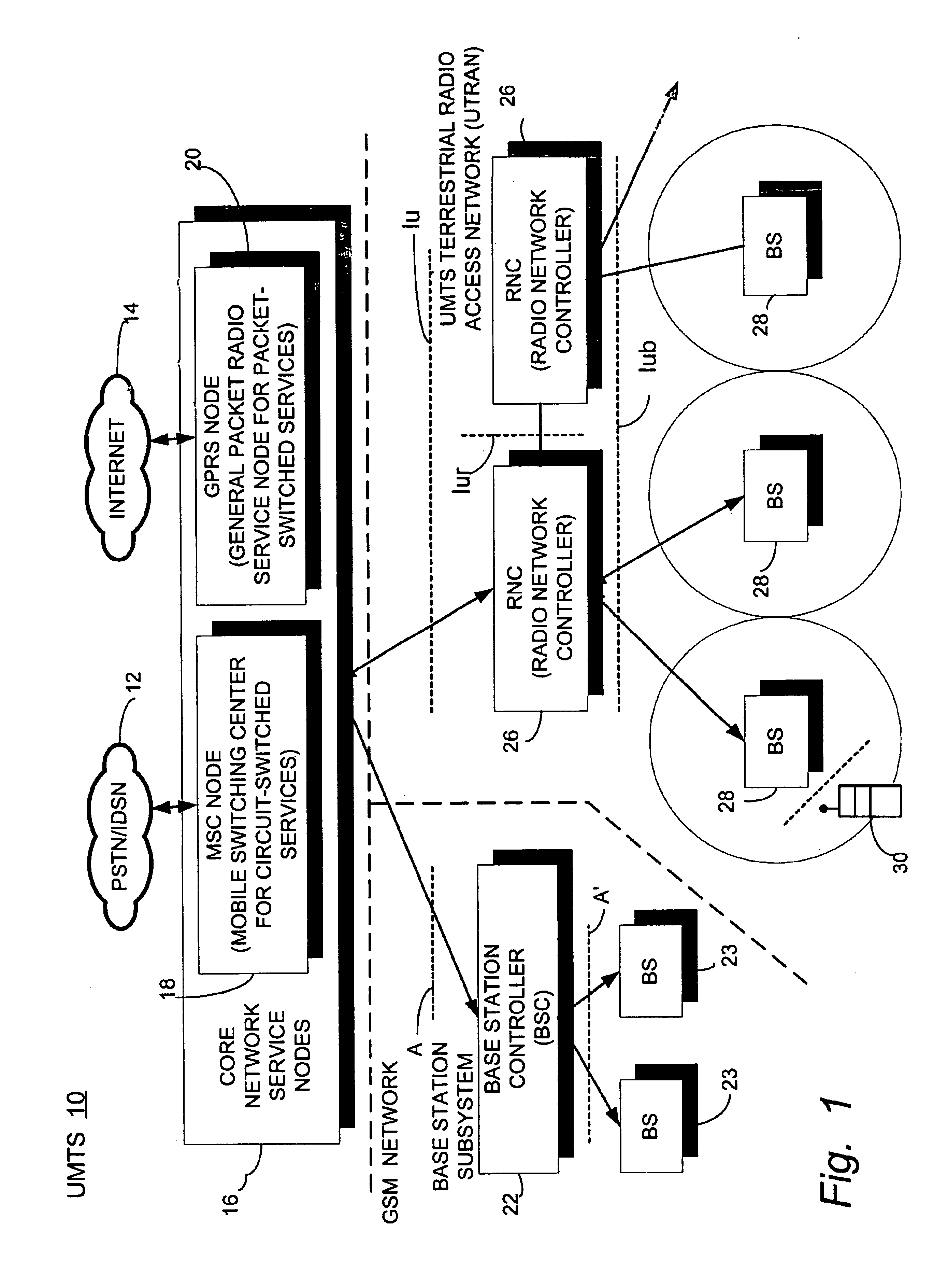
The present invention is described in the non-limiting, example context of a universal mobile telecommunications (UMTS) 10 shown in FIG. 1. A representative, connection-oriented, external core network, shown as a cloud 12 may be for example the Public Switched Telephone Network (PSTN) and / or the Integrated Services Digital Network (ISDN). A representative, connectionless-oriented external core network s...


PUM


Abstract

A telecommunications network performs an inter-frequency hard handover for a connection with a user equipment unit (UE) by switching either from a cell or a current active set of base stations on a first frequency to a virtual active set of base stations on another (new) frequency. The inter-frequency hard handover can be an inter-frequency handover within a same system, or an inter-system handover. The virtual active set of base stations is maintained at the user equipment unit (UE), and is updated in accordance with one of several updating implementations of the invention. In a first mode of the invention for implementing virtual active set updates, the network authorizes the user equipment unit (UE) to report to the network the occurrence of certain network-specified events which are acted upon by the network for communicating virtual active set update information to the user equipment unit (UE). In a second mode of the invention, the network authorizes the user equipment unit (UE) to perform an autonomous virtual active set update upon occurrence of certain network-specified events, with inter-frequency events being reported from the equipment unit (UE) to the network and the network issuing an inter-frequency handover command. Advantageously, events which trigger intra-frequency measurements can be reused for reporting inter-frequency measurements. In another of its aspects, the present invention provides the network with a quality estimate for a current active set as well as a quality estimate for the virtual active set. The quality estimate can be utilized in a context of a handover from one UTRAN frequency to another UTRAN frequency, or even in the context of an inter-system handover (e.g., a handover between a UTRAN system and a GSM system, for example). The quality estimate can be utilized to trigger a change or switch of frequencies / systems. Certain thresholds employed in the quality estimate-utilizing handovers provide hysteresis protection.

Description

BACKGROUND1. Field of the InventionThe field of the invention is wireless communications. The present invention pertains to inter-frequency handover and inter-frequency measurement reporting.2. Related Art and Other ConsiderationsIn a typical cellular radio system, a geographical area is divided into cell areas served by base stations which are connected to a radio network. Each user (mobile subscriber) in the cellular radio system is provided with a portable, pocket, hand-held, or car-mounted mobile station (user equipment unit or UE) which communicates voice and / or data with the mobile radio network. Each base station includes a plurality of channel units including a transmitter, a receiver, and a controller and may be equipped with an omnidirectional antenna for transmitting equally in all directions or with directional antennas, each directional antenna serving a particular sector cell. Each user equipment unit (UE) also includes a transmitter, a receiver, a controller, and a us...

Claims


Application Information

Patent Timeline
Patent Type & Authority Patents(United States)
IPC IPC(8): H04Q7/38H04W36/18H04W36/30
CPCH04W36/18H04W36/30H04W36/06H04W36/0055H04W36/0058H04W12/06
Inventor MULLER, WALTER G. A.
Owner TELEFON AB LM ERICSSON (PUBL)
Why Eureka
Try Eureka